Flowserve PT Series Limitorque User Manual
Page 10
Limitorque PT Series Worm Gear Operator FCD LMENIM2001-00 – 01/10
10
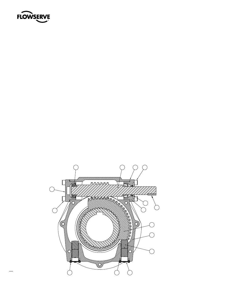
2.7 Setting Position Limit Stops - PT65, 120, 150
Refer to Figure 2.4.
1. Remove the Stop Plates (pc# 9) and Stop Plate Gaskets (pc# 10) to expose the Stop Screws (pc# 7)
2. Remove the outboard Stop Screws
3. Turn the inboard Stop Screw counterclockwise to back the screw away from the Drive Sleeve/Worm Gear
4. Place the valve disk in the full closed position (pointer will point to the full closed marking on the Gear Housing)
5. Turn the Stop Screw in the clockwise direction until the end of the screw contacts the Drive Sleeve/Worm Gear
6. Install the outboard Stop Screw and tighten firmly against the inboard Stop Screw to secure the closed set position
7. Move the valve disk to the full open position
8. Follow steps 3 through 6
a
CaUTIOn: If the valve is operated with an electric actuator/gear operator combination, and the valve is position-
seated, set the actuator limit switches to trip prior to engagement of the PT Drive Sleeve/Worm Gear with the
Stop Screws. Damage to the operator could result from the Drive Sleeve/Worm Gear contacting the Stop Screw
under motorized operation.
note: The stops are adjustable to +/- 5º of total travel to allow for proper positioning of the worm gear quadrant.
Figure 2.4 – Setting Position Limit Stops – PT65, 120, 150
5
19
8
23
2
1
7
9
10
20
6
11
18
3
21