Flowserve PT Series Limitorque User Manual
Page 8
Limitorque PT Series Worm Gear Operator FCD LMENIM2001-00 – 01/10
8
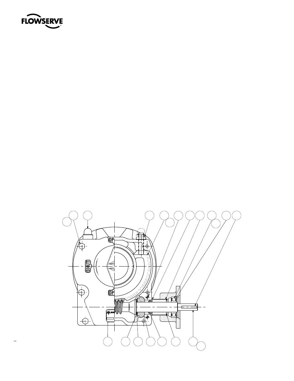
2.5 Setting Position Limit Stops - PT12, 14, 30, 40, 50, 75
Refer to Figure 2.2.
1. Remove the two Stop Screw Caps (pc# 10) (if supplied) to expose the Stop Screws (pc# 11).
2. Loosen the Stop Adjusting Nut on the Stop Screw and adjust the screw by turning it counterclockwise to back the
screw away from the Worm Gear Quadrant (pc# 12)
3. Place the valve disk in the full closed position
4. Turn the Stop Screw (pc# 11) in the clockwise direction until the end of the screw contacts the Worm Gear
Quadrant (pc# 12)
5. Tighten the Stop Adjusting Nut to secure the closed set position
6. Move the valve disk to the full open position
7. Follow steps 2 through 5
a
CaUTIOn: If the valve is operated with an electric actuator/gear operator combination, and the valve is position-
seated, set the actuator limit switches to trip prior to engagement of the PT Drive Sleeve/Worm Gear with the
Stop Screws. Damage to the operator could result from the Drive Sleeve/Worm Gear contacting the Stop Screw
under motorized operation.
note: The stops are adjustable to +/- 5º of total travel to allow for proper positioning of the worm gear quadrant.
Figure 2.2 – Setting Position Limit Stops – PT12, 14, 30, 40, 50, 75
11
-
5 5
0
C
03
-
00
1
10
09
04
05
06
02
08
07
SERIAL No:
FULLY GREASE
DIVISION OF
12
13
02B
16
17 18
09B
14
12A
15
03
16B