Flowserve PT Series Limitorque User Manual
Page 11
11
Limitorque PT Series Worm Gear Operator FCD LMENIM2001-00 – 01/10
flowserve.com
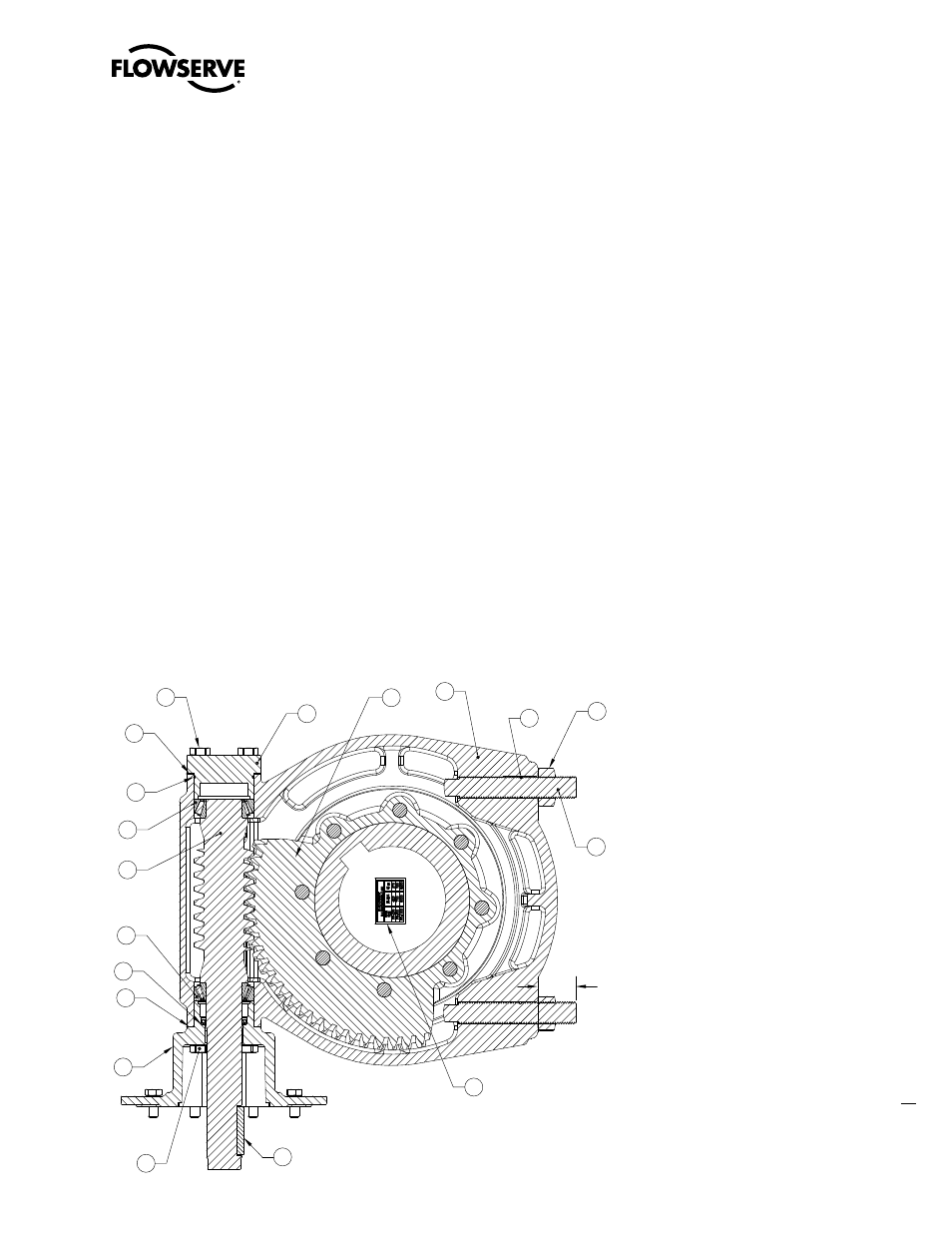
2.8 Setting Position Limit Stops – PT250, 500, 1000
Refer to Figure 2.5.
1. Loosen the Stop Adjusting Nut (pc# 11)
2. Turn the Stop Adjusting Screw (pc# 10) counterclockwise to back the screw away from the Drive Sleeve/Worm
Gear (pc# 3)
3. Place the valve disk in the full closed position (pointer will point to the full closed marking on the Gear Housing, pc# 1)
4. Turn the Stop Adjusting Screw in the clockwise direction until the end of the screw contacts the Drive Sleeve/Worm
Gear
5. Tighten the Stop Adjusting Nut to secure the closed set position
6. Move the valve disk to the full open position
7. Follow steps 1 through 5
a
CaUTIOn: If the valve is operated with an electric actuator/gear operator combination, and the valve is
position-seated, set the actuator limit switches to trip prior to engagement of the PT Worm Gear with the
Stop Screws. Damage to the operator could result from the Worm Gear contacting the Stop Screw under
motorized operation.
note:
The stops are adjustable to +/- 5º of total travel to allow for proper positioning of the worm gear quadrant.
Figure 2.5 – Setting Position Limit Stops – PT250, 500, 1000
2X 2.29
ASSEMBLE STOPS
TO THIS DIMENSION
Wormshaft & Stops
Scale 1 : 3
25
15
7
15
8
9
6
2
6
21
45
17
1
3
11
10
12
22