System malfunctions – Flowserve NRS 1-40 User Manual
Page 18
18
System Malfunction 3
System Malfunctions
– continued –
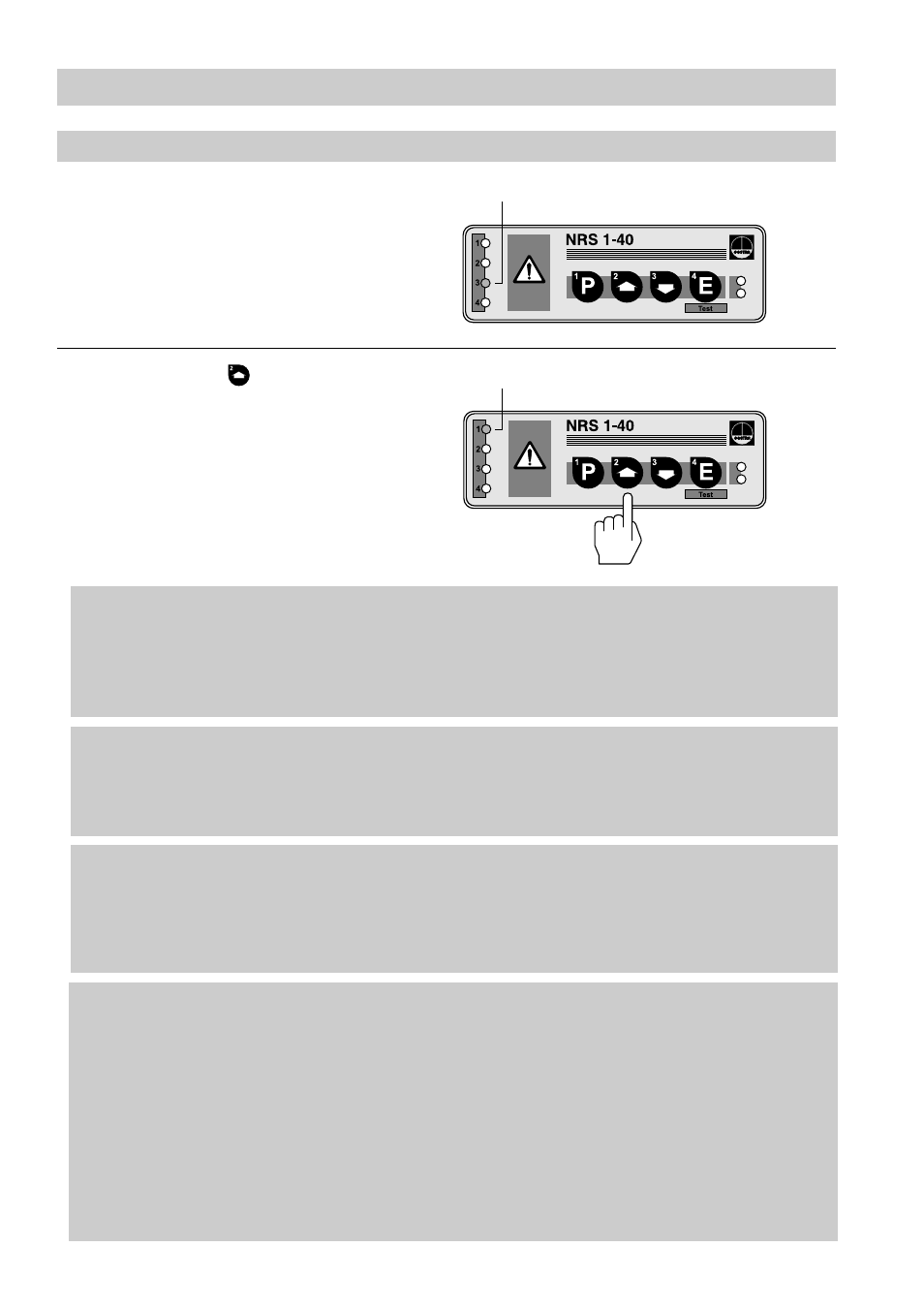
LED 3 flashes slowly.
A communication malfunction in the
bus line has been detected.
LED 3 flashes slowly
LED 1 flashes rapidly
Hold down button .
LED 1 flashes rapidly.
A bus communication malfunction
between level switch and level
electrode 1 has been detected.
Fault:
The data transfer between level switch and electrode is interrupted.
Remedy: Make sure that the bus lines are wired in accordance with the wiring
diagram (observe polarity). All end-of-line devices must be provided
with a terminating resistor of 120
Ω
! (see wiring diagram).
Cut off power supply and re-start the system after 5 sec.
Fault:
The baud rate of one or more bus devices is not set correctly.
Remedy: Check baud rate settings of all bus devices. The baud rate settings
must be identical. Please refer to section “Annex”.
Cut off power supply and re-start the system after 5 sec.
Fault:
The overall length of the bus line does not correspond to the baud rate
setting.
Remedy: Change baud rate settings of all bus based equipment as described under
“Annex”.
Cut off power supply and re-start the system after 5 sec.
Fault:
In spite of correct wiring and commissioning of the equipment an
interference signal is indicated.
Remedy: The interference signal is caused by H. F. interferences coming from the
installation. For interference suppression of the voltage supply we supply
ferrite rings, stock code 147253. The 230 V supply lines should be looped
through the ferrite ring five to ten times. If several controllers are used in
the system, they can be fed from the interference suppressed supply
lines. For the interference suppression of the bus line we supply hinged-
shell ferrite rings, stock code 147254. The hinged-shell ferrite rings are
clamped onto the bus line close to the terminal strip of the controller.
Restart the system after installation.