Wiring diagram, Fig. 2 fig.1 – Flowserve NRS 1-40 User Manual
Page 3
Advertising
3
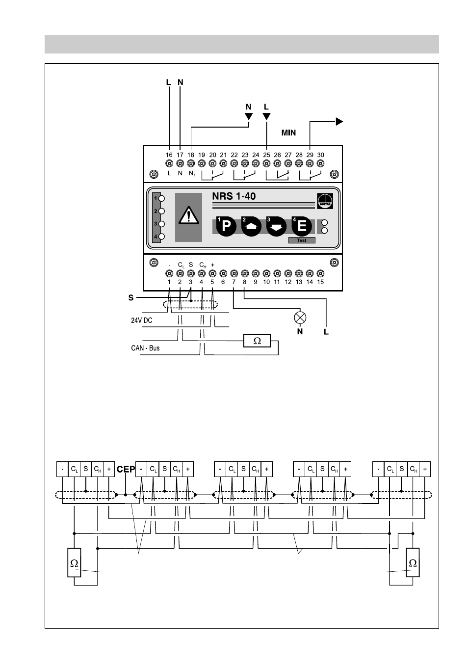
Wiring Diagram
Fig. 2
Fig.1
Control terminal
URB 1
Switching
controller
NRS 1-40
Controller
. . .
Level electrode
NRG 16-40
Terminating resistor
120
Ω
Voltage supply
CAN data line
Terminating resistor
120
Ω
Protection circuit
– uninterrupted –
Twisted pair cable
Twisted pair cable
Photo-Mos output
24 V- 230 V AC/DC, 100 mA
Instantaneous LW alarm,
clocked malfunction signal
Further safety
equipment
Note:
The NRS 1-40 is
the first equipment
of the safety chain.
All relay contacts are
internally linked.
Level sensor
NRG . . .
Terminating resistor
120
Ω
Advertising
See also other documents in the category Flowserve Hardware:
- Tandem Seal (8 pages)
- 978 Chemiepac (12 pages)
- ISC2 Single Pusher Repair (8 pages)
- LS-300 Series Durametallic (4 pages)
- Pac-Seal Type 16 (8 pages)
- U Series BW Seals (4 pages)
- ISC2 Dual Pusher Repair (12 pages)
- ISC2 Single metal bellows seal (8 pages)
- Durametallic Double CRO (8 pages)
- VRA-C Series Durametallic (4 pages)
- ISC2 Dual metal bellows sea (12 pages)
- Single Inside Pusher Type Seal (8 pages)
- Bearing Gard (2 pages)
- X-200 (12 pages)
- GTS Series (12 pages)
- MSS Series (12 pages)
- SLC Series Interseal (12 pages)
- QB Series BW Seals (8 pages)
- SLM-6100 (12 pages)
- SLM-6200 (12 pages)
- High Temperature Metal Bellows Seals (8 pages)
- X Series BW Seals (8 pages)
- ML-200 Series Durametallic (8 pages)
- ML-200 Series Durametallic (8 pages)
- Circulator (12 pages)
- ISC Series (16 pages)
- Gas Barrier Control System (4 pages)
- CPM Series (12 pages)
- CPM Series (8 pages)
- Mechanical Seal and Seal Support System Storage (4 pages)
- RIS Seal (12 pages)
- 682 Seal Cooler (8 pages)
- ISC2 Series (8 pages)
- ISC2 Series (116 pages)
- Pac-Seal Type 52 (8 pages)
- Pac-Seal Type 31 (8 pages)
- ST Series (8 pages)
- Mechanical Seal General (16 pages)
- Dual Pressurized Seals (8 pages)
- Uniseal Series BW Seals (8 pages)
- XLC Series (8 pages)
- PSS II Durametallic (8 pages)
- PSS II (16 pages)
- ISC1SX (8 pages)
- ISC1PX (8 pages)