Annex, Switching controller level electrode, Emergency operation – Flowserve NRS 1-40 User Manual
Page 24
24
Danger
The terminal strip of the NRS 1-40 is live during operation.
This presents the danger of electric shock.
Cut off power supply before fixing or removing the equipment.
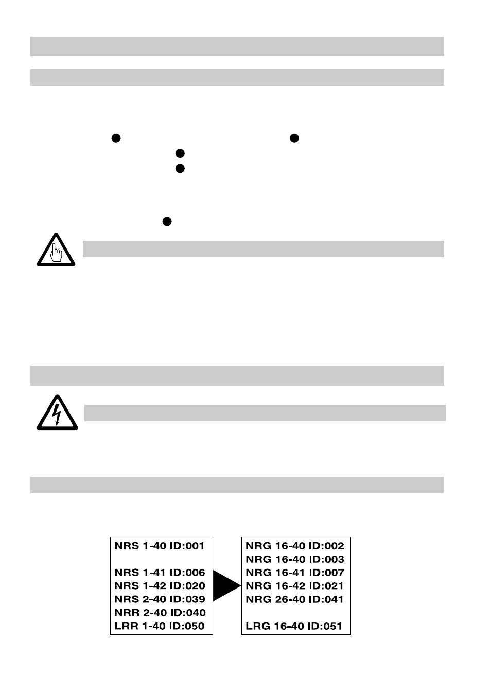
Annex
Factory set default node IDs
The individual node IDs must be manually adjusted on the equipment.
Please observe the installation instructions of the device in question.
Switching
controller
Level electrode
If one level electrode fails to operate the installation can continue to operate in
emergency mode under constant supervision according to TRD 401 with one level
electrode.
1. Undo screws and remove the lower terminal strip , Fig. 4.
2. Set code selector switches “S1”and “S2” to “
OFF
”, Fig. 6, Fig. 8.
3. Set code selector switches “S1” to “
ON
” and “S2 - S7” to “
OFF
”. The switching
controller NRS 1-40 has now the node ID “1”, Fig. 7.
4. Set node ID of the working electrode to “2” (cf. section “Emergency operation”
in the Installation Manual for level electrodes NRG 16-40, 17-40, 19-40).
5. Affix lower terminal strip .
■
Enter beginning of emergency operation in the boiler log.
■
An installation operating in emergency mode has to be constantly
supervised.
■
Install a visible sign or signal in the control room to indicate emergency
operation.
■
Immediately replace faulty level electrode.
■
Enter end of emergency operation in the boiler log.
Attention
B
Emergency Operation
8
9
A
A
Emergency operation of water-level limiting system