Testing transducer linearity – Fluke Biomedical DPM1B User Manual
Page 21
Pneumatic Transducer Tester
Testing Transducer Linearity
11
To interpret the results, proceed to the following three sections:
•
Testing Transducer Linearity
•
Transducer Sensitivity Test
•
Testing Other Devices
DPM-1B
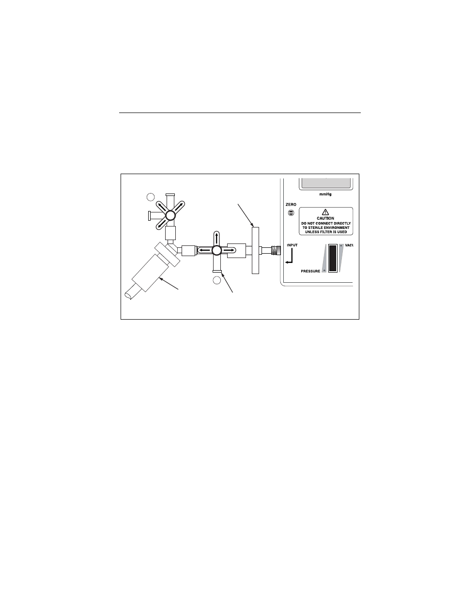
Filter
2
1
Test Transducer
Vent Port
ehf4.eps
Figure 4. DPM1B Configured to Apply Pressure to Transducer
Testing Transducer Linearity
Several measurements are required to determine if a transducer is
linear over a range of pressure. See Figure 5 for a sample plot of
transducer linearity determined by using the Tester Pneumatic
Transducer Tester.
1. Test the transducer for linear operation in the range of
20 mmHg to 190 mmHg, for example, by taking measurements
in increments of 10 mmHg from 20 mmHg to 190 mmHg (as
shown in Figure 5).
2. Plot the resulting pressures by placing the Tester readings in
one axis and the monitor readings in the other axis.
3. Draw a line through the plotted points. A straight line indicates
that the transducer operates linearly; a curved line indicates
that the transducer operates nonlinearly.
4. Compare the actual pressure measurements with the
transducer manufacturer’s specifications for linear operation.