2 layout – Foxconn A76ML Series User Manual
Page 11
4
1
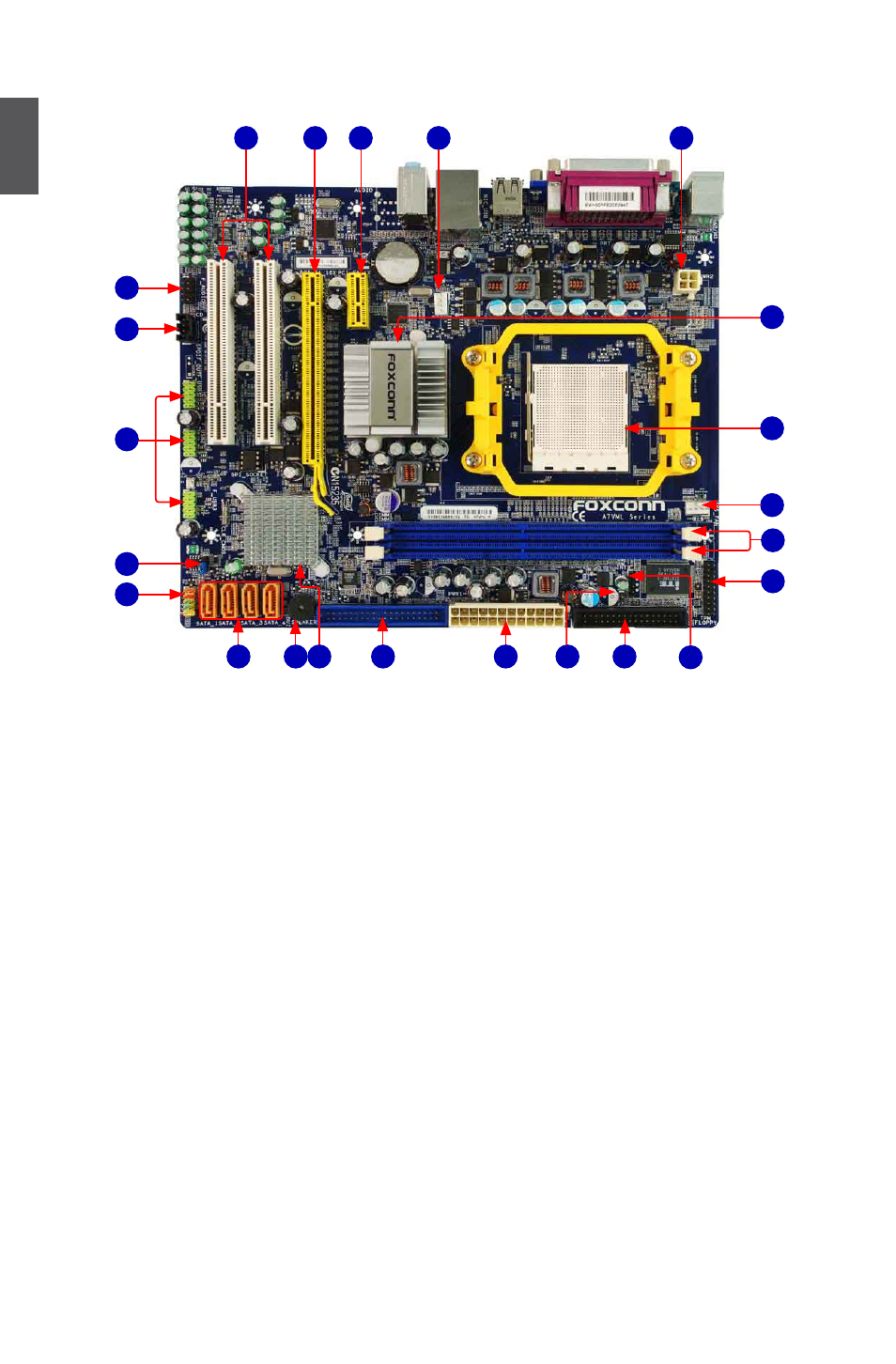
1-2 Layout
1. 4-pin ATX 12V Power Connector
2. CPU fan Header
3. PCI Express x1 Slot
4. PCI Express x16 Slot
5. PCI Slots
6. Front Audio Connector
7. CD_IN Connector
8. Front USB Connectors
9. Clear CMOS Jumper
10. Front Panel Connector
11. SATA Connectors
12. Speaker Connector (or Buzzer)
13. South Bridge: AMD SB700(A7VML, A7VML-K)
AMD SB710 (A76ML, A76ML-K)
14. IDE Connector
15. 24-pin ATX Power Connector
16. Chassis Intrusion Alarm Header
17. Floppy Connector
18. IrDA Connector
19. TPM Connector
20. DDR2 DIMM Slots
21. System fan Header
22. CPU Socket
23. North Bridge: AMD 780V (A7VML, A7VML-K)
AMD 760G (A76ML, A76ML-K)
Note : The above motherboard layout is for reference only, please refer to the physical
motherboard for detail.
11
12
7
15
14
18
1
2
4
3
5
8
13
22
10
6
17
21
20
23
16
9
19