Fronius Symo 10-20 kW User Manual
Page 12
10
Cross-section of
the AC cable
When using an M32 metric screw joint (reducer removed):
cable diameter 11 - 21 mm
(with a cable diameter of 11 mm the strain-relief force is reduced from 100 N to a maximum
of 80 N)
With cable diameters greater than 21 mm, the M32 screw joint must be replaced by an M32
screw joint with a larger clamping area - item number: 42,0407,0780 - strain-relief device
M32x15 KB 18-25.
Connecting the
inverter to the
public grid (AC)
IMPORTANT! The PE ground conductor of the AC cable must be laid in such a way that it
is the last to be disconnected in the event that the strain-relief device should fail.
This can be ensured, for example, by making it somewhat longer and by laying it in a loop.
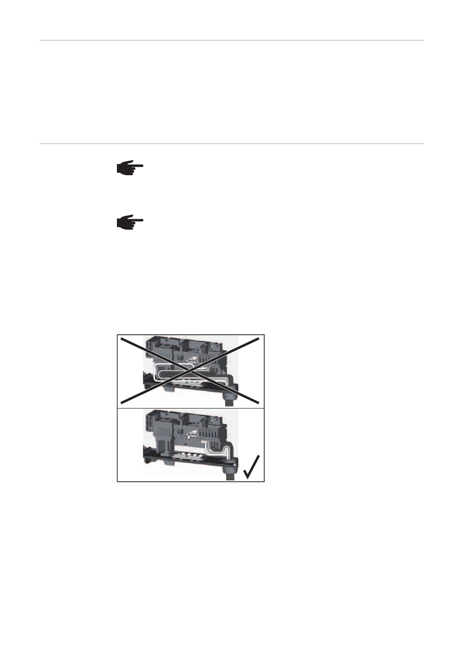
If AC cables are laid over the shaft of the
DC main switch or across the connection
block of the DC main switch, they may be
damaged when the inverter is swung in, or
they may even prevent the inverter from
being swung in.
IMPORTANT! Do not lay AC cables over
the shaft of the DC main switch or across
the connection block of the DC main switch!
NOTE! Form loops with the AC cables when connecting them to the AC termi-
nals.
When securing the AC cables using a metric screw joint, ensure that the loops do
not protrude beyond the connection area. Under certain circumstances it may oth-
erwise no longer be possible to close the inverter.
NOTE!
-
Ensure that the grid neutral conductor is grounded. In the case of IT networks
(insulated networks with no grounding) this may not be the case; it will then
not be possible to use the inverter.
-
In order to use the inverter, the neutral conductor must be connected.
A neutral conductor that is too small may adversely affect the ability of the
inverter to feed energy into the grid. The neutral conductor must therefore be
the same size as the other live conductors.