System requirements, Cable distance limitations, Installation – GAI-Tronics GC-AC1 EZ Page Industrial Intercom User Manual
Page 2
Pub. 42004-307G
EZ
P
AGE
I
NDUSTRIAL
I
NTERCOMS
Page 2 of 16
f:\standard ioms - current release\42004 instr. manuals\42004-307g.doc
03/15
The setting of an internal jumper and the external wiring interconnection scheme are different in a
balanced system and an unbalanced system. Refer to the appropriate installation instructions provided in
this manual.
System Requirements
Each unit requires local power within approximately 9.5 feet of unit for interconnection of unit’s
audio/control cable to system cable.
N
OTE
: If applicable local electrical codes permit, the use of a combined UL-approved junction box for
termination of the unit’s local power connection
and audio/control to system cable could be
helpful.
Cable Distance Limitations
N
OTE
: Calculations are based on the use of No.
18 AWG twisted pair wire.
Audio Pair
Maximum distance from the line balance is
approximately 1 mile (1.6 km). Maximum
distance between the two end units is approximately 2 miles (3.2 km).
External Control Pair
Maximum distance between the two end units is approximately 2 miles (3.2 km).
System Cable
Recommend use of twisted, two pair cable (No. 18 AWG) between stations for maximum system
hum/noise immunity. Extreme hum/noise areas may require shielded twisted, two pair cable.
Installation
Since a good installation is important in obtaining the best possible performance of the communications
system, determine the operating mode of each unit and carefully plan the overall installation before actual
work is started. Read the entire procedure and the many suggestions offered to help you plan your
installation.
WARNING
Please adhere to all the following safety and operating instructions on the
unit and in the installation manual:
Ensure that the installation is in accordance with all local applicable electrical codes.
Disconnect power to the unit before opening or servicing to avoid possible damage to equipment or
personal injury.
Avoid running system cable near high voltage/high electromagnetic sources.
Avoid servicing the unit during electrical storms.
Do not touch non-insulated wires.
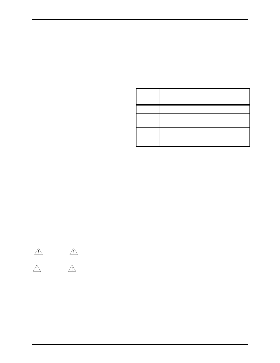
Models
Input
Voltage
Interconnection
(Customer-supplied)
GC-AC1
120 V ac
NEMA 5-15R style receptacle
GC-DC1
12-16 V dc Small junction box for Class 2
wiring
GC-AC2
230 V ac
Small UL-approved junction
box or plug rated for this
voltage
DANGER
Do not install in a hazardous area. Use in safe, non-classified, non-hazardous
areas only.