Internal settings – GAI-Tronics GC-AC1 EZ Page Industrial Intercom User Manual
Page 3
Pub. 42004-307G
EZ
P
AGE
I
NDUSTRIAL
I
NTERCOMS
Page 3 of 16
f:\standard ioms - current release\42004 instr. manuals\42004-307g.doc
03/15
Internal Settings
The following procedure describes how to change the internal settings. If the intercom will be used as a
Listen/Talk unit or as a Master unit in a balanced line system, then no changes to the internal PCBA’s
jumper or switch settings are required.
WARNING
Disconnect power to unit before opening to avoid possible damage to equipment or personal injury.
1. Disconnect power to the unit.
2. Loosen and remove the six screws securing the front cover.
3. Lift out the front panel assembly and tilt to the left. Use caution to ensure that no unnecessary strain
is placed on the attached wiring harnesses.
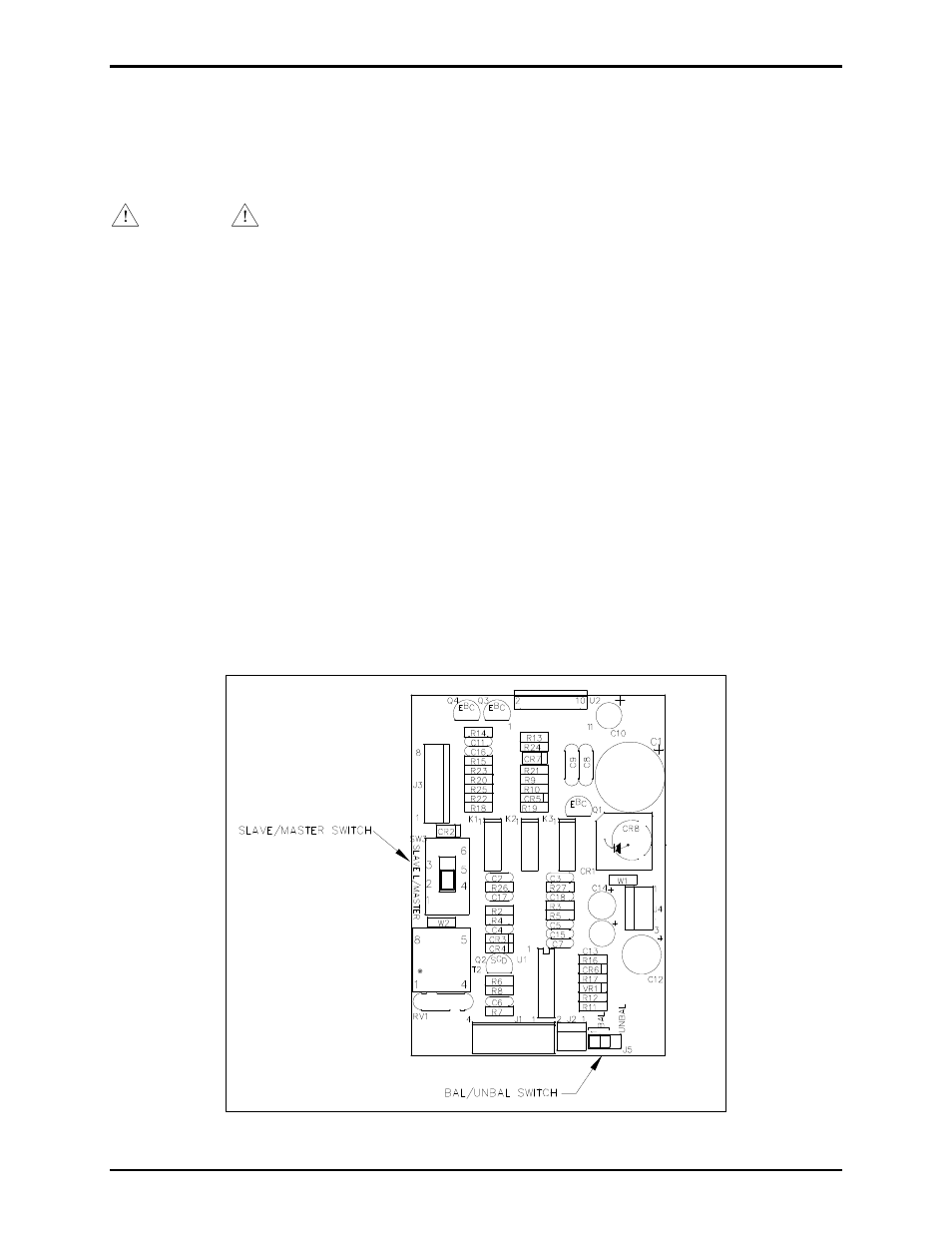
4. If configuring the unit as a slave, slide the PCBA’s mode switch (SW3) to the S
LAVE
position. See
Figure 2.
5. If operating in an unbalanced cable system, reposition the PCBA’s jumper P5/J5 from the B
AL
position to the U
NBAL
position. See Figure 2.
6. Reinsert the front panel assembly into the rear housing. Ensure that no wires are between the front
panel’s gasket and the housing’s sealing surface that could be pinched.
7. Reinsert the six screws into the front cover and tighten securely.
8. Reapply the unit power and check for proper operation.
Figure 2. PCBA Outline Detail