GAI-Tronics 12584-002 I/O Control Module User Manual
Page 6
Pub. 42004-388B
Model 12584-002 I/O Control Module
Page: 6 of 15
\\s_eng\gtcproddocs\standard ioms - current release\42004 instr. manuals\42004-388b.doc
04/07
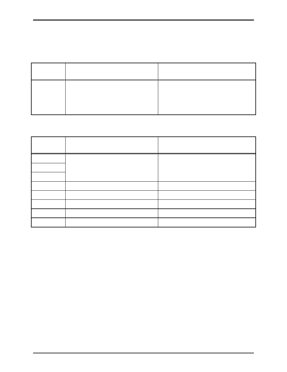
Switch Settings for Remote I/O Applications
When the I/O Control Module is being used for remote input/output control or for alarm activation and
reset from a master control device, the switches must be set as follows:
Table 5. Hex Switch Settings for Serial Data Control
Hex
Switch No.
Function
Settings
S1 and S2
Address - TBD by system master
controller
A unique address must be set for each I/O
control module in the system. As
determined by the system master control
device. Device addressing should be set in
sequential order starting with address 01.
Table 6. DIP S4 Switch Settings: Serial Data Control
DIP
Switch S4
Function
Settings
S4-1
S4-2
S4-3
Baud rate to be determined by system
master controller’s baud rate.
See Table 1.
Baud rate must be set to match the master
controller.
S4-4 N/A
N/A
S4-5 N/A
N/A
S4-6
Wait for poll request from master
Closed
S4-7
Return address to master controller
Open
S4-8
Do not signal data fault with master
Closed
Reset Switch
A small push-button switch is provided to restart the I/O controller’s microprocessor. Momentarily press
the button to initiate the reset sequence.