GAI-Tronics 12584-002 I/O Control Module User Manual
Page 8
Pub. 42004-388B
Model 12584-002 I/O Control Module
Page: 8 of 15
\\s_eng\gtcproddocs\standard ioms - current release\42004 instr. manuals\42004-388b.doc
04/07
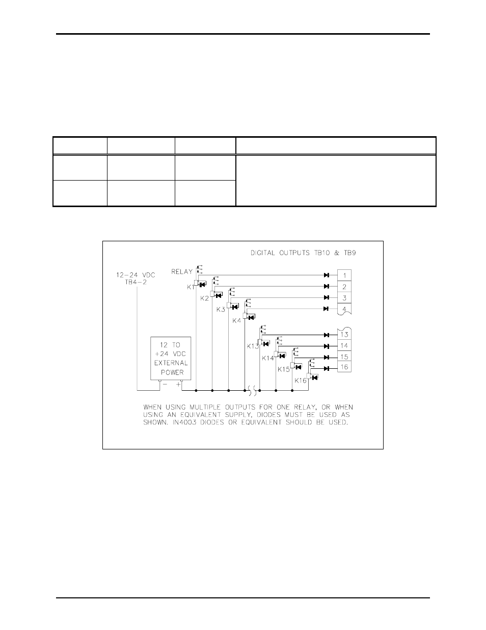
TB10 and TB9 - Digital Output Connections
The TB10 and TB9 connectors each provide 16 digital (common ground) output connections designed to
drive externally-mounted relays or other indicating circuits. Each output can sink up to 100 mA of
current. External circuitry (relays, indicators, etc.) must be powered from an external power supply of the
same voltage used to power the I/O Control Module (12 to 24 V dc). The ground (or dc common)
terminals of the external power supply must be tied to TB4 (-).
Table 10. TB9 and TB10 Digital Output Connections
Terminal Labeled
Function Specifications
TB10-1 to
TB10-16
O
UT
-1
TO
16
Digital outputs
1-16
TB9-1 to
TB9-16
O
UT
-17
TO
32
Digital outputs
17-32
• Active Low State - sinks 100 mA (max) to GND.
• Active High State - output floats high to source
voltage.
Figure 2. Typical digital output relay wiring