Mechanical receipt inspection, Cable installation safety considerations, Required tools – GAI-Tronics 10370-701 VoIP Interface/Amplifier Assemblies User Manual
Page 20: Amplifier components
Pub. 42004-463A
Model 10370-70x and 10370-80x VoIP Interface/Amplifier Assemblies
Page 18 of 23
f:\standard ioms - current release\42004 instr. manuals\42004-463a.doc
09/13
Mechanical Receipt Inspection
The Speaker Interfaces are shipped in a cardboard container, protected from movement and distress by a
self-forming packaging material. Thoroughly inspect it as soon as possible after delivery. In-transit
damage should be immediately reported to the transportation company.
Cable Installation Safety Considerations
Interconnecting, communications, and Class 2 dc power cables should be separated from electrical light
or other Class 1 circuits by at least 2 inches. The exception is where Class 1 wiring or power circuits are
run in a raceway, or are metal-sheathed or metal-clad, or are permanently separated from the conductors
of the other circuitry by a continuous and firmly fixed nonconductor such as porcelain tubes or flexible
tubing in addition to the insulation on the wire. Communications cables and in-building wiring should be
listed and marked for the purpose according to NEC Article 800.
Required Tools
#1 Phillips screwdriver
1/16-inch flat blade screwdriver (for TB101, TB1 and TB3 connections only)
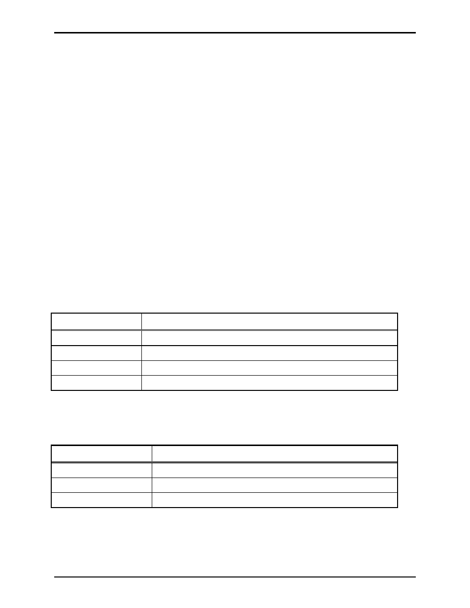
Amplifier Components
The Model 10370-801 and 10370-802 WiFi Speaker Interfaces contain the following components:
Table 4.
Part No.
Description
69868-001
WiFi Module PCBA
69625-001
VoIP Amplified Speaker PCBA
100-02-7013-000 VoIP
PCBA
120/240 V ac input, switching power supply, 60 W, 24 V dc output
The Model 10370-701 and 10370-702 VoIP Speaker Interfaces contain the following components:
Table 5.
Part No.
Description
69625-001
VoIP Amplified Speaker PCBA
100-02-7013-000 VoIP
PCBA
120/240 V ac input, switching power supply, 60 W, 24 V dc output