Operation, Software configuration, How to diagnose assembly/model faults – GAI-Tronics 12578-002 Monitored Input Module (MIM) User Manual
Page 10
Pub. 42004-711L2B
Model 12578-002 Monitored Input Module (MIM)
Page 10 of 12
f:\standard ioms - current release\42004 instr. manuals\42004-711l2b.doc
01/09
Operation
The operation of the Model 12578-002 MIM is controlled by the MCU configuration. See the MCU
configuration details in the system manual for all operation information.
Software Configuration
69248-xxx
Jumper must be removed from P1 to operate in a MIM configuration.
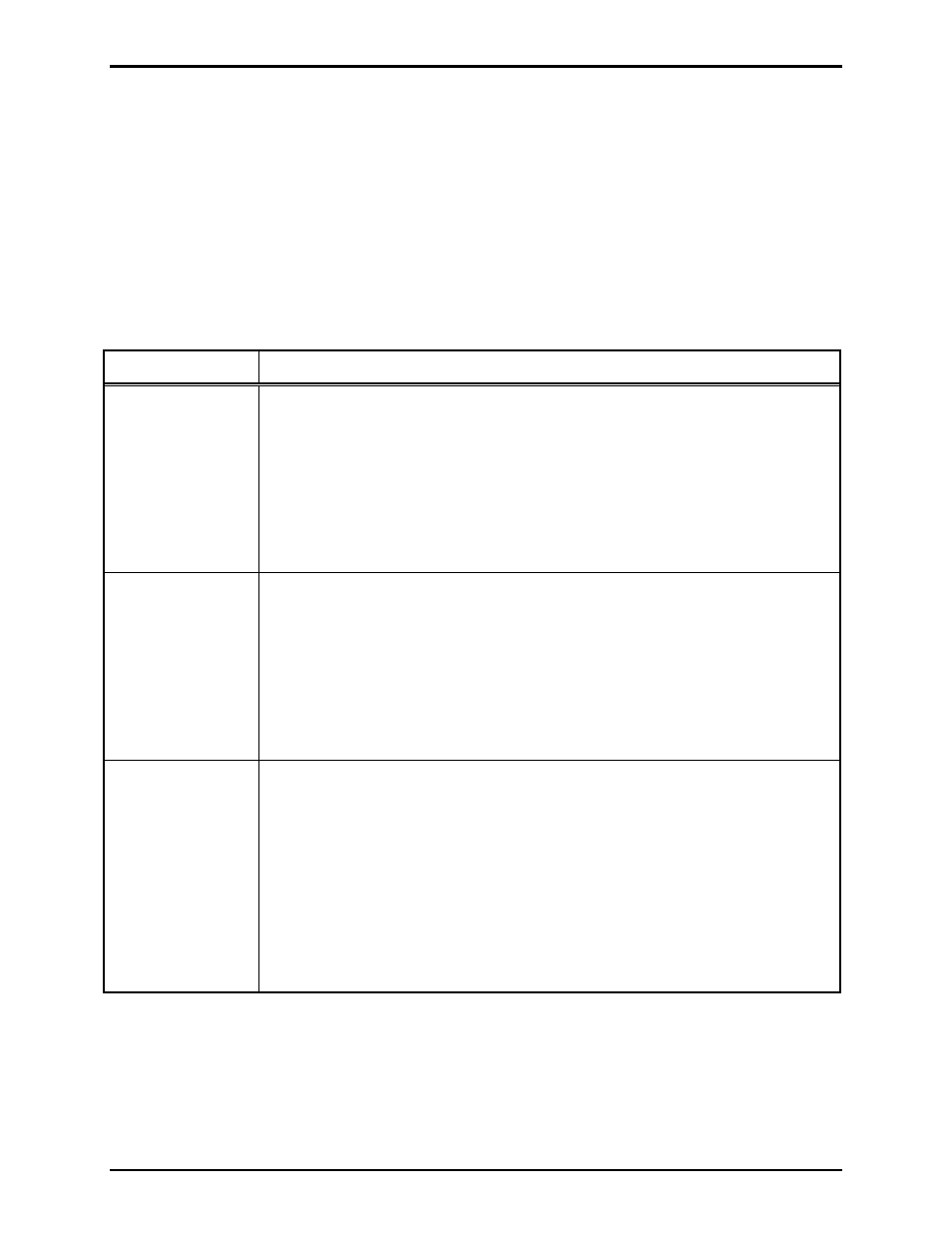
How to Diagnose Assembly/Model Faults
Symptom Action
MIM does not
communicate
with MCU
• Verify power is applied to the MIM.
• Verify RS-485 is connected to the MIM.
• Verify RS-485 is properly terminated at the last device in the RS-485 link.
• Verify address of MIM agrees with the setup configuration.
• Ensure CPU PCBA is correctly connected via J2.
• Call for service of the MIM.
MIM does not
recognize dry
inputs
• Verify total loop resistance is less than 100 Ω.
• Verify power is applied to the MIM.
• Verify RS-485 is connected to the MIM.
• Verify RS-485 is properly terminated at the last device in the RS-485 link.
• Verify end of line resistor(s) properly installed on each input circuit.
• Call for service of the MIM.
MIM does not
activate an
alarm with 24 V
dc applied to
input terminal.
(Wet contact
mode ONLY.)
• Verify that the jumper that selects the proper “_ V dc when active” mode is in
the correct position for the desired mode. Refer to Mode 5- IDC Non-
Supervision (Wet Contact) information.
• Verify that the applicable input jumpers have been repositioned for WET
operation.
• Verify that the input is within the acceptable dc voltage range (20–30 V dc)
• Verify that the proper voltage polarity has been observed for external
connections to the input terminals.
• Call for service of the MIM.