GAI-Tronics 12578-002 Monitored Input Module (MIM) User Manual
Page 5
Pub. 42004-711L2B
Model 12578-002 Monitored Input Module (MIM)
Page 5 of 12
f:\standard ioms - current release\42004 instr. manuals\42004-711l2b.doc
01/09
Inputs
The MIM contains eight individually configurable inputs, allowing it to interface with field devices.
Connections with these field devices are made at connectors TB1 through TB8. Each connector
corresponds to a single input (TB1 is used for input #1, TB2 is used for input #2, etc.) Each one of these
inputs may be configured to operate in one of five input modes.
Each input mode requires a unique connection scheme between the external field devices and the
appropriate input connector on the MIM. The connection scheme for each input mode is indicated below.
Since the connection scheme is independent of which input is used, only input #1 will be discussed.
To ensure proper termination, ferrules must be crimped on the end of all conductors that are
terminated on the terminal blocks. The size of the ferrule is dependent upon the size of the
conductor used and may be sourced from any supplier such as Phoenix, Altec or Weidmuller.
The terminal blocks may accept conductors between sizes No. 28 AWG to 12 AWG.
Mode 0: Deactivate Circuit
In this mode, input #1 is not used and is not monitored by the MIM. If this mode is used, no external
connections should be made to connector TB1.
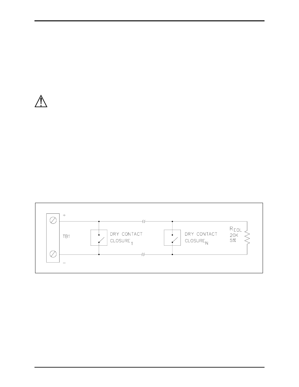
Mode 1: IDC Line Supervision Multiple Switch
In this mode any number of normally-open dry contact closures may be installed on the line. The loop is
monitored for ground faults and open circuits in Mode 1. The end-of-line device is a 20 k
Ω, 5% tolerance
resistor.
Figure 2. IDC Line Supervision Multiple Switch
N
OTE
: The 20 k
Ω, 5% tolerance resistor is not included with the MIM. This resistor is included in a kit
(12509-003), which must be ordered separately.