Installation, Mounting, Wiring – GAI-Tronics 379-001 Monitored Relay Module (MRM) Station User Manual
Page 3: Power
Pub. 42004-714L2C
Model 379-001 Monitored Relay Module Station
Page: 3 of 9
f:\standard ioms - current release\42004 instr. manuals\42004-714l2c.doc
08/11
Installation
CAUTION
Do not install this equipment in hazardous areas other than those indicated on the approval listing
in the “Specifications” section of this manual. Such installation may cause a safety hazard and
consequent injury or property damage. Disconnect power before installing or removing the MRM.
Mounting
The Model 379-001 MRM Station enclosure is not supplied with conduit or cable gland holes since cable
quantity, size, and entry location vary with each installation.
Drill or punch openings at the required locations before mounting the enclosure. Typically multiple
cables entries are required for SmartSeries Page/Party
®
system cable and input wiring. Refer to the
Wiring section below. Use caution when drilling or punching the enclosure to avoid damaging the
internal components. Bottom cable entry is recommended to prevent moisture from entering the
enclosure and dripping onto the terminals or circuit boards.
Mount the enclosure to a suitable surface using appropriate customer-supplied hardware. Refer to Figure
1 for mounting hole dimensions.
Remove the shipping tie-wrap that is securing the PCBA to its mounting Snaptrack.
Wiring
The MRM Station is parallel-wired to the Page/Party
®
system cable in the same fashion as SmartSeries
handset/speaker stations. The system cable distributes ac power, party line audio and page line to the
stations. The MRM requires only ac power and page line connections from the system cable. Spare
terminals are provided for the unused conductors in the system cable. A separate cable(s) is generally
used for the input connections. Each connection is explained below.
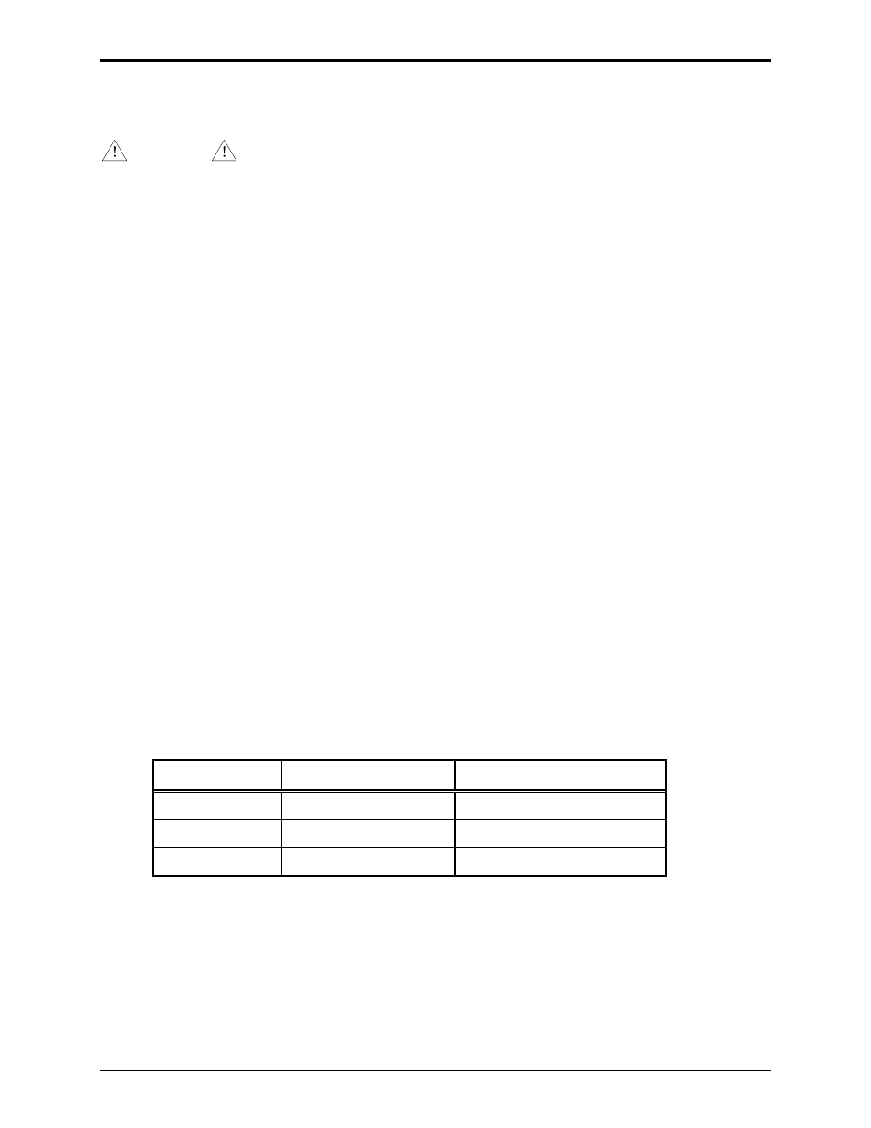
Power
120 V ac power is connected to terminal block TB13 at the top of the panel. Refer to Figure 1. AC
power is accessed from the Page/Party
®
system cable per the following table.
Function
Terminal Block
System Cable Wire Color
AC Line (hot)
TB13-1
Black
Neutral TB13-2
White
Ground TB13-3 Green/yellow