Mode 2: idc single normally-open (n.o.) switch – GAI-Tronics 379-001 Monitored Relay Module (MRM) Station User Manual
Page 5
Pub. 42004-714L2C
Model 379-001 Monitored Relay Module Station
Page: 5 of 9
f:\standard ioms - current release\42004 instr. manuals\42004-714l2c.doc
08/11
If either cable leg is grounded, or if a cable break occurs on either leg, the 20 k
Ω load is removed
indicating a fault condition.
N
OTE
: The 20 k
Ω, 5% tolerance resistor is not included with the MRM. This resistor is included in the
Model 12509-003 Kit, which is sold separately.
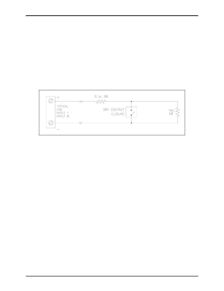
Mode 2: IDC Single Normally-Open (N.O.) Switch
In this configuration, only one normally open voltage-free contact closure may be installed and a 5.1 k
Ω
and 15 k
Ω resistor must be wired in series/parallel with the contact. The cable is monitored for open
circuits, wire-to-wire short circuits (across + and −), and ground faults. When the contact is inactive
(open), the line appears as 20.1 k
Ω load (15 kΩ in series with 5.1 kΩ). This indicates a healthy inactive
cable loop.
Figure 3. Single normally-open switch
When the contact closed, the 15 k
Ω resistor is bypassed. The circuit then sees only the 5.1 kΩ load,
indicating an active input.
If there is a short across + and −, if either cable leg is grounded, or if a cable break occurs on either leg,
the 20 k
Ω load is removed indicating a fault condition.
N
OTE
: The terminating resistors are not included with the MRM. These resistors are included in the
Model 12509-003 Kit, which is sold separately.