Mode 3: idc single normally-closed (n.c.) switch, Mode 4: iac line supervision – GAI-Tronics 379-001 Monitored Relay Module (MRM) Station User Manual
Page 6
Pub. 42004-714L2C
Model 379-001 Monitored Relay Module Station
Page: 6 of 9
f:\standard ioms - current release\42004 instr. manuals\42004-714l2c.doc
08/11
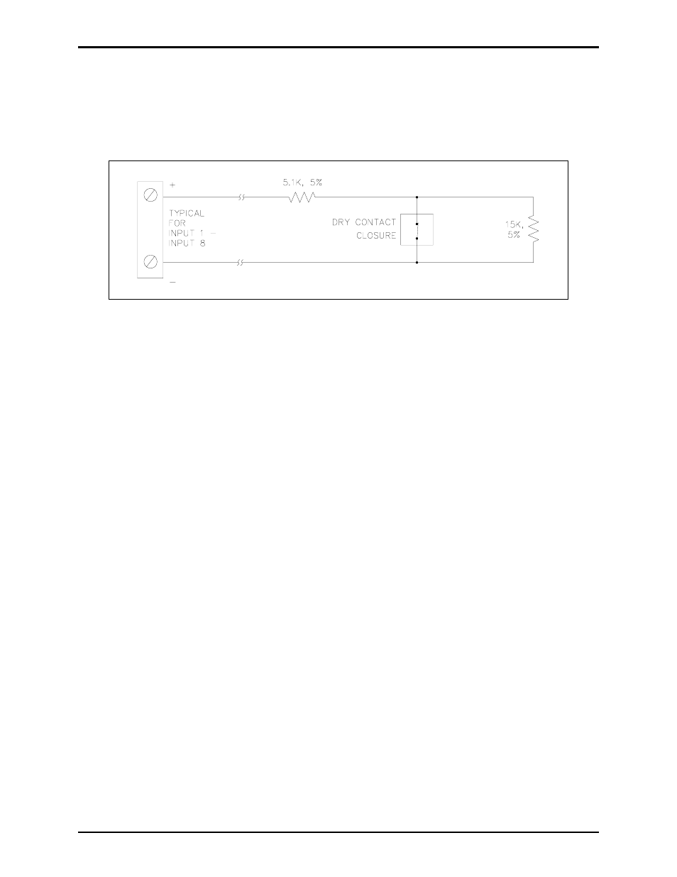
Mode 3: IDC Single Normally-Closed (N.C.) Switch
In this configuration, only one normally closed voltage-free contact may be installed and a 5.1 k
Ω and 15
k
Ω resistor must be wired in series/parallel with the contact. The cable is monitored for open circuits,
wire-to-wire short circuits (across + and −), and ground faults. When the contact is closed, the 15 k
Ω is
bypassed and the circuit sees only the 5.1 k
Ω load. This indicates a healthy inactive cable loop.
Figure 4. Single normally-closed switch
When the contact opens, the circuit then sees 20.1 k
Ω load (15 kΩ in series with 5.1 kΩ), indicating an
active input.
If there is a short across + and −, if either cable leg is grounded, or if a cable break occurs on either leg,
the 20.1 k
Ω load is removed indicating a fault condition.
N
OTE
: The terminating resistors are not included with the MRM. These resistors are included in the
Model 12509-003 Kit, which is sold separately.
Mode 4: IAC Line Supervision
In this mode, multiple strobe lights may be installed across the common relay terminals. Total strobe
current draw cannot exceed 5A. A 20 k
Ω 2W resistor must be installed across the last strobe. The strobe
power source is connected to the normally open relay terminals. The normally closed relay terminals are
connected to the corresponding input terminals. (Relay 1 to Input 1, Relay 2 to Input 2, etc.) Refer to
Figure 5 and Figure 6 below.
During an inactive condition, the input circuit monitors the strobe cable for open circuits, short circuits
and ground faults. Under normal conditions the line appears as 20 k
Ω load, indicating a healthy cable
loop.
During an active condition, the relay contacts change state. The input circuit is isolated from the strobe
cable and power is applied to activate the strobes. The cable loop is not monitored during active relay
conditions.