Inputs, Mode 0: deactivate circuit – GAI-Tronics 379-001 Monitored Relay Module (MRM) Station User Manual
Page 4
Pub. 42004-714L2C
Model 379-001 Monitored Relay Module Station
Page: 4 of 9
f:\standard ioms - current release\42004 instr. manuals\42004-714l2c.doc
08/11
Page Line
The page line twisted pair in the Page/Party
®
system cable serves as the data line between the MRM and
the ADVANCE System Control Cabinet. The page line connections are made to the MRM module per
the following table. Refer to Figure 1 for terminal locations.
Function
MIM Terminal Block System Cable Wire Color
Page Line (L1)
TB 11 (L1)
Red/blue
Page Line (L2)
TB 11 (L2)
Blue/red
Inputs
Input connections (from voltage-free contacts or switched 24 V dc voltage sources) are made to screw
terminals TB1 through TB8 on the input PCBA. Refer to Figure 1 for terminal locations.
To ensure proper termination, ferrules should be crimped on the end of all input wires prior to
connecting the MRM terminal blocks. The terminal blocks may accept No. 28–2 AWG
conductors.
Each input is wired to operate in one of five input configurations (modes) that is set via system
programming. Each mode requires a unique connection scheme between the external field device and the
corresponding input terminals on the MRM. The connection scheme for each input mode is described
below. Since the each input operates independently, only input 1 will be discussed. Inputs 2–8 are
identical.
Mode 0: Deactivate Circuit
The input circuit is disabled via system programming. No external connections may be made to
connector TB1.
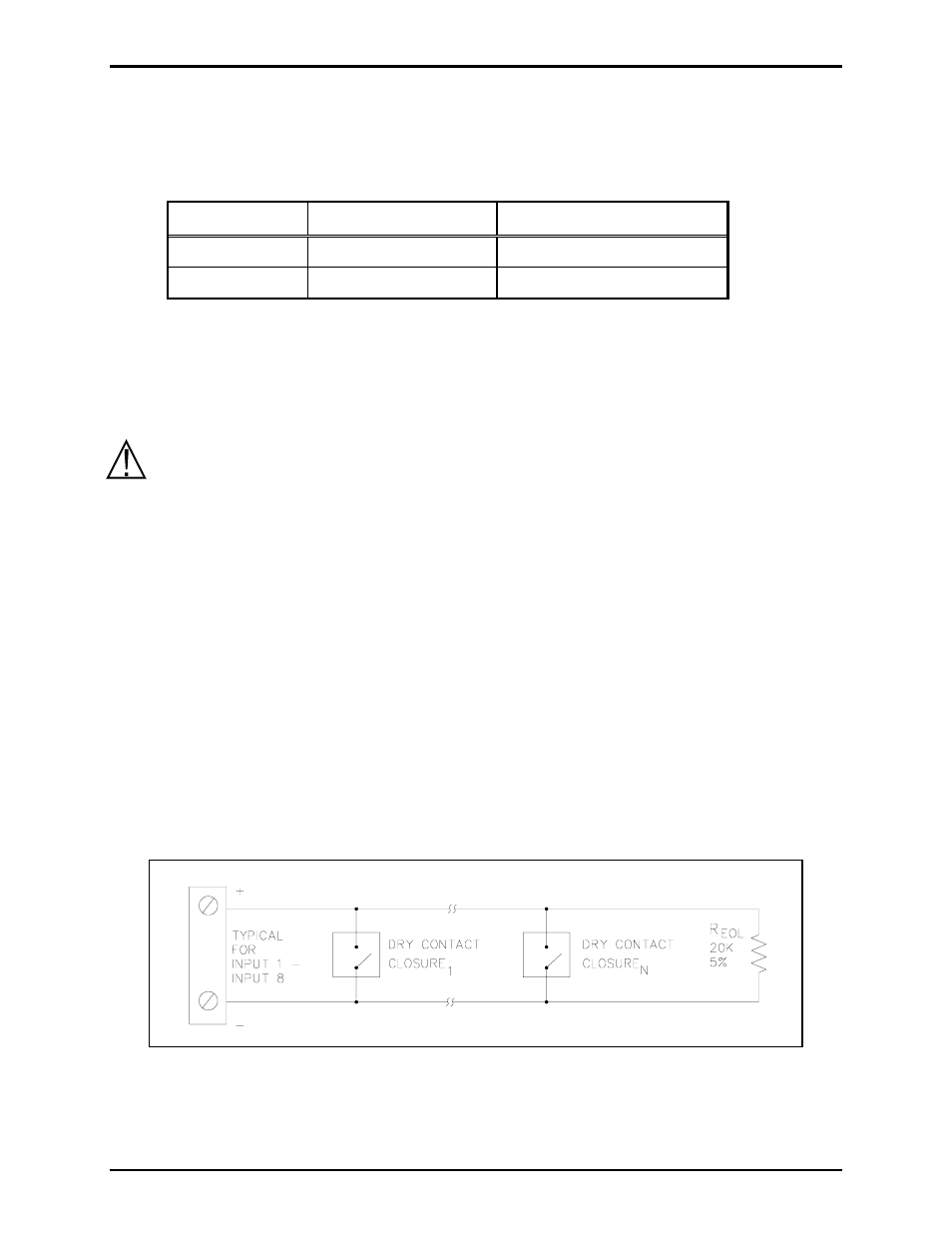
Mode 1: IDC Line Supervision (Multiple Switches)
In this mode, any number of normally open voltage-free contact closures may be installed on the input
line and a 20 k
Ω resistor must be installed across the last contact. The cable is monitored for ground
faults and open circuits. When the contacts are inactive (open), the line appears as 20 k
Ω load. This
indicates a healthy inactive cable loop.
Figure 2. Multiple normally-open switches
When any contact is closed, the 20 k
Ω resistor is bypassed. The input circuit is shorted, indicating an
active input.