Motorola commandplus hardware installation, Icpn9000 navigator mcu – GAI-Tronics XCP0100A 4-Channel Expansion Kit User Manual
Page 5
Pub. 43003-021E
Model XCP0100A 4-Channel Expansion Kit
Page 5 of 7
f:\radio products-current release\43003\43003-021e\43003-021e.doc
03/12
Motorola CommandPLUS Hardware Installation
Use the hardware supplied in the envelope labeled “Motorola Brand Hardware.”
1. Using the #4-40
5/16-inch screws, mount the three #4-40 standoffs to the rear of the panel in the
three holes located at the top and bottom of the panel next to the existing CLP board.
2. Insert the #10-32
1 ½-inch screw through the #10 washer, the surge protection cable’s ring lug, the
bottom-right hole of the CLP board, the #10-32 standoff, and through the panel. Secure the assembly
from the other side of the panel using the remaining #10 washer and the #10-32 nut.
3. Secure the CLP board to the rear-panel standoffs using the three #4-40
3/16-inch screws in the
remaining three holes.
4. Remove the earth ground terminal screw from the bottom right corner of the existing CLP board and
attach the other end of the surge protection cable to the earth ground screw.
5. Mount the new CSD board next to the existing CSD board(s) using the M3
6 mm screws and #4
washers.
ICPN9000 Navigator MCU
1. Disconnect the power from the ICPN9000 Navigator Series MCU and remove all attached cables
from the rear cover.
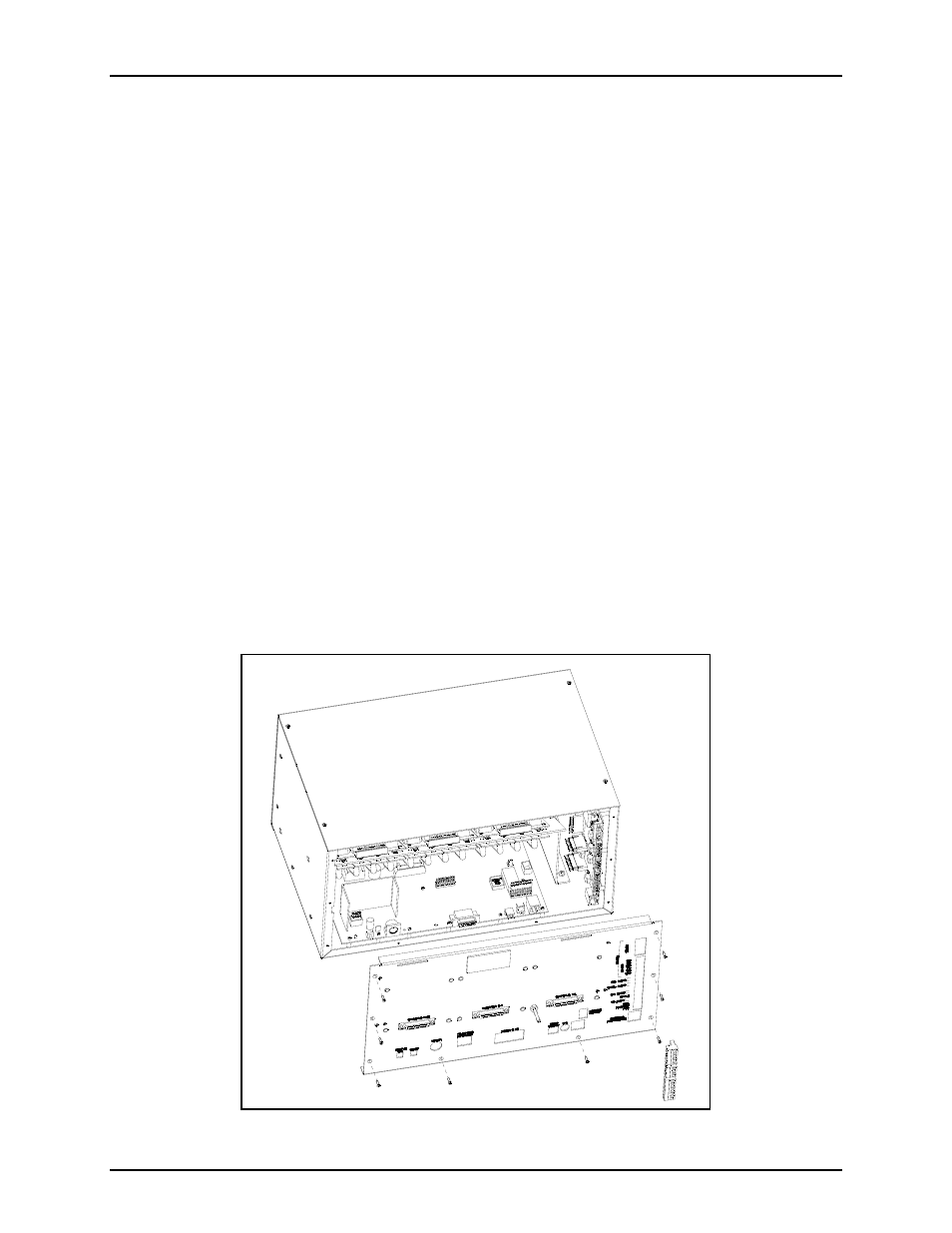
2. Remove the eight screws securing the rear panel. Gently pull the rear cover from the housing and
disconnect the ribbon cables (SLV-CBL-P) attached to the surge suppression PCBA. Lay the rear
panel flat. See Figure 4.
Figure 4.