GAI-Tronics XCP0100A 4-Channel Expansion Kit User Manual
Page 7
Pub. 43003-021E
Model XCP0100A 4-Channel Expansion Kit
Page 7 of 7
f:\radio products-current release\43003\43003-021e\43003-021e.doc
03/12
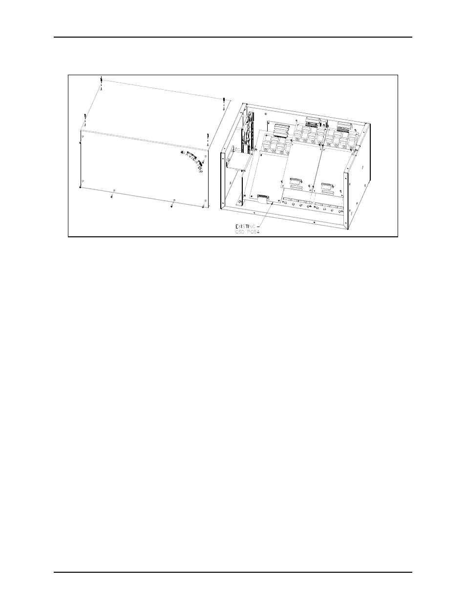
7. Remove the 10 screws securing the side cover panel and gently lift the cover off. See Figure 6.
Figure 6.
8. Mount the new CSD PCBA next to the existing CSD board(s) using the supplied #4-40 screws. Refer
to Figure 6.
9. Connect the supplied CSD-to-CPM ribbon cable to J1 and route it under the cable slot nearest the
mounting position. Plug the other end of the cable into either P2 on the CPM board, if expanding a 4-
channel console, or P3 on the CPM board if expanding an 8-channel console.
10. Reassemble the side cover panel using the reverse procedure. Verify the correct ribbon cable
positioning before tightening the slave mid-panel mounting screws to avoid damage to the cable.
11. Refer to the CARD Suite Software (found on the XAC4000A Programming Bundle CD) for
programming instructions specific to the new channels.