GAI-Tronics XCP0100A 4-Channel Expansion Kit User Manual
Page 6
Pub. 43003-021E
Model XCP0100A 4-Channel Expansion Kit
Page 6 of 7
f:\radio products-current release\43003\43003-021e\43003-021e.doc
03/12
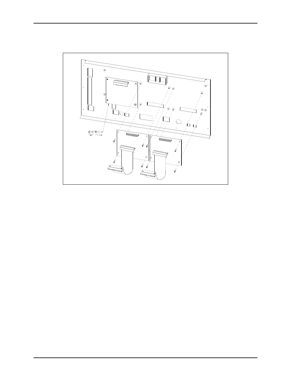
3. Mount the new CLP PCBA next to the existing CLP board using the four threaded stand-offs with the
#4-40 screws provided. See Figure 5.
Figure 5. Inside of Rear Cover
N
OTE
: Only one module is provided with each kit.
4. Remove the earth ground terminal screw from the bottom right corner of the existing CLP PCBA.
Attach the supplied surge protection cable to the earth ground screw, and the other end to the
matching location on the new CLP PCBA.
5. Attach the SLV-CBL-P ribbon cable to its matching connectors between the CLP PCBA at J25 and
the CSD PCBA at P25. Also reattach the original ribbon cable.
6. Replace the rear cover and screws ensuring that no cables are pinched between the main enclosure
and the rear cover.
- 370-201, 372A Interface Amplifier Assembly (10 pages)
- 13314-001 and 13314-002 Div. 2 Hazardous Area Speaker Assembly using 13314 Driver (3 pages)
- 230-001 Pole-Mounting Kit (3 pages)
- Electro Sound Electro-Sound Communication System (9 pages)
- 13314-004 Div. 2 Hazardous Area 100-Volt Horn Driver (5 pages)
- XGM003A Gooseneck Microphone Kit (2 pages)
- XGM003A Gooseneck Microphone Kit (26 pages)
- XGM003A Gooseneck Microphone Kit (5 pages)
- 9974 Junction Box (5 pages)
- 232-001 Pole Mounting Kit (3 pages)
- 13411-001 and 13411-002 Replacement Voice Coil / Diaphragm Assemblies (5 pages)
- 726-101 Single Party Desktop Subset (5 pages)
- 726-101 Single Party Desktop Subset (4 pages)
- 478-002 Centra-Page Desktop Subset (6 pages)
- 239WM-002 Slim Wall-Mount Stanchions (5 pages)
- 239WM-002 Slim Wall-Mount Stanchions (6 pages)
- 239WM-002 Slim Wall-Mount Stanchions (4 pages)
- 239WM-002 Slim Wall-Mount Stanchions (4 pages)
- 210-001 Corridor Telephone (10 pages)
- 239WM-002 Slim Wall-Mount Stanchions (10 pages)
- Speaker / Horn Installation for GAI-Tronics Communication System (8 pages)
- 700 Series 120 V AC Page/Party Systems (10 pages)
- 700 Series 24 V DC Page/Party Systems (14 pages)
- 703-002 Multi-Party 24 V DC Amplifier Enclosures (13 pages)
- 703A Indoor Multi-Party 115 V AC Amplifier Enclosure (8 pages)
- 703A Indoor Multi-Party 115 V AC Amplifier Enclosure (3 pages)
- 723-003 24 V DC Remote Handset/Speaker Amplifier (7 pages)
- 723-001 Remote Handset / Speaker Amplifier (3 pages)
- 237-001 Plug-in Power Supply for Telephones (3 pages)
- 733-002 Single Party 24 V DC Amplifier Enclosure (13 pages)
- 7855-001 Explosion-proof Handset Stations (13 pages)
- 7855-002 24 V DC Explosion-proof Page/Party Handset Stations (14 pages)
- 670-001 Explosion-proof Page/Party Speaker Station (9 pages)
- 670-002 24 V DC Explosion-proof Page/Party Speaker Station (10 pages)
- 13351 Integral Loudspeakers (5 pages)
- 305-001 Line Balance Assembly (3 pages)
- 272-001 Intrinsically-Safe Telephones (13 pages)
- 713-102 24 V DC Page/Party Remote Speaker Amplifier (5 pages)
- 263-000 Isolation Barrier Unit (I.S. Phone) (14 pages)
- 774-001 Portable Station Enclosure (Page/Party) (5 pages)
- 234SBA 234SBA Stanchion Broadcast Assembly (12 pages)
- 491-204 Mine Dial / Page Phone (10 pages)
- 773-001 Outdoor Jack Station (Page/Party) (3 pages)
- 491 Series Mine Dial / Page Phone Interface Cabinet (23 pages)
- 268-001 Intrinsically-Safe Telephone Rack-Mount System (14 pages)