Installation, Pre-starting checks, Motor maintenance – Greenheck Fabricated Pressure Blower (471833) User Manual
Page 3: Wheel and fastener maintenance, Affects of installation on performance, Figure 1, Figure 2, Figure 3, Viewed from drive side of the fan, Wheel viewed from drive side of the fan
3
Model FPB Fabricated Pressure Blower
®
Installation
Move the fan to the desired location and fasten
securely through mounting holes provided in the base
angles. The unit must be set level (shimming may be
necessary). Flexible duct connections and vibration
isolators should be used where noise is a factor.
The motor voltage and
ampere rating must be
checked for compatibility with
the electrical supply prior to
final electrical connection.
Supply wiring to the fan
must be properly fused and
conform to local and National
Electrical Codes.
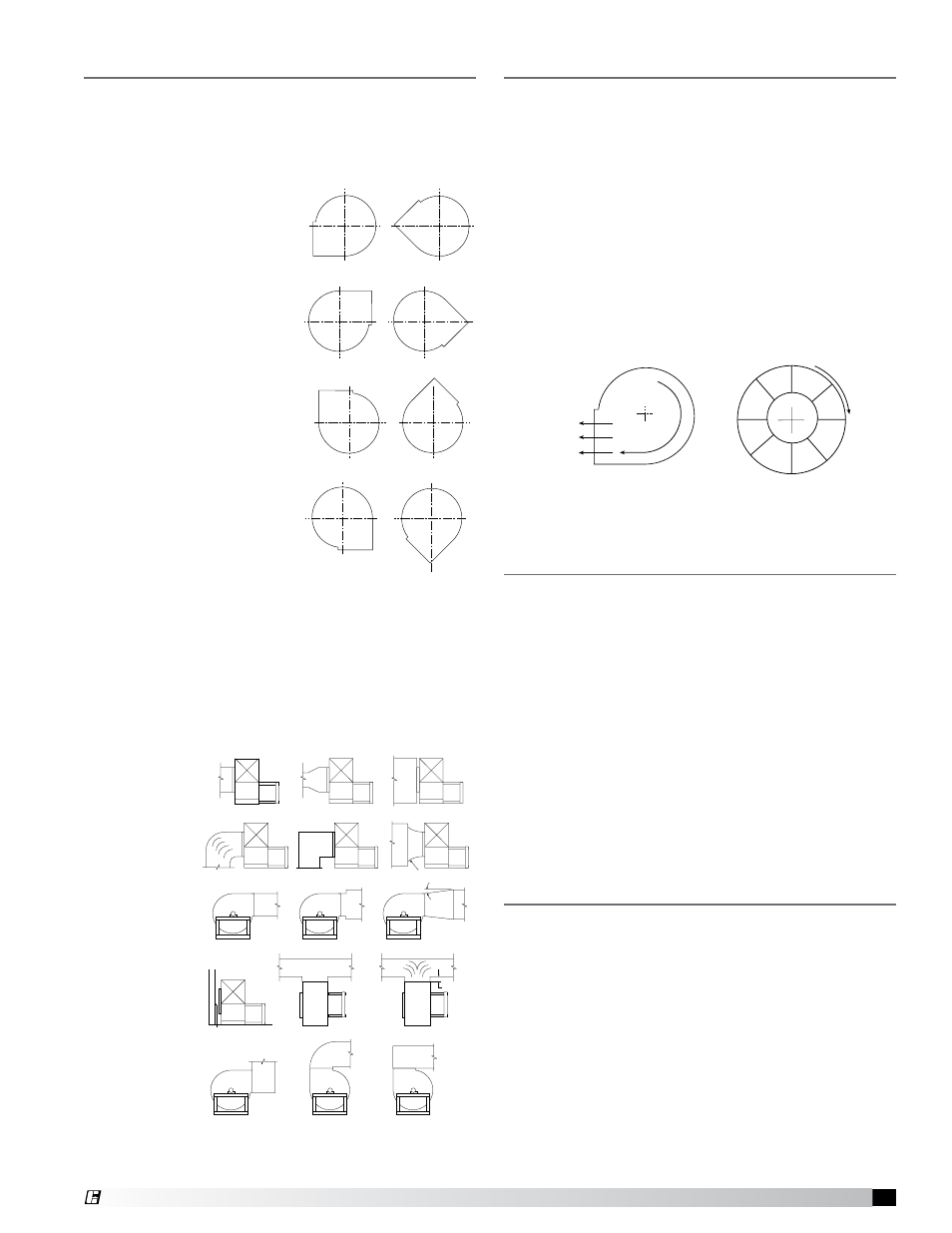
The rotation and discharge
is factory set to clockwise
rotation with a bottom
horizontal discharge, but can
be rotated to other discharge
positions or wheel rotations
in the field if necessary.
Removal of the housing
bolts allows the discharge
to be rotated to the various
clockwise positions. See
Figure 1. Clockwise rotation
shown. Counterclockwise
discharge positions are a
mirror image of those shown.
CW BH
CW BAU
CW TAU
CW UB
CW TH
CW TAD
CW BAD
CW DB
Figure 1
Viewed from
drive side of the fan
Affects of Installation on Performance
Restricted or unstable flow at the fan inlet can cause
pre-rotation of incoming air or uneven loading of the
fan wheel, yielding large system losses, increased
sound levels
and structural
failure of the
fan wheel.
Free discharge
or turbulent
flow in the
discharge
ductwork will
also result in
system effect
losses.
The examples
(Figure 2) show
the system
layout and inlet
and discharge
configurations
which can
affect fan
performance.
Good
Poor
Poor
Good
Poor
Good
Good
Good
Good
Poor
Poor
Good
Good
Poor
Poor
Not greater than 60°
included angle
Distance should be at
least 1/2 dia.
ONE FAN DIA.
7° Max.
Figure 2
Pre-Starting Checks
Wheels must rotate freely and not rub on the inlet
collar. Rotation direction of the wheel is critical
and incorrect rotation will result in reduced air
performance, increased motor loading and possible
motor burnout.
Check wheel rotation by momentarily energizing the
unit. Wheel rotation should be in same direction as
the airflow at the outlet and conform to the rotation
diagram below (Figure 3). Wheel rotation can be
reversed by switching the polarity of the motor. To do
this with a 3 phase motor, interchange 2 of the 3 leads.
For single phase motor, consult the motor wiring
diagram.
Motor Maintenance
Motor maintenance is generally limited to cleaning
and lubrication (where applicable). Cleaning should be
limited to exterior surfaces only. Removing dust and
grease build-up on the motor housing assures proper
motor cooling. Use caution and do not allow water or
solvents to enter the motor. Under no circumstances
should motors be sprayed with steam, water or
solvents.
Greasing of motors is intended only when fittings
are provided. Many fractional horsepower motors
are permanently lubricated for life and require no
further lubrication. Motors supplied with grease
fittings should be greased in accordance with the
manufacturer’s recommendations.
Wheel and Fastener Maintenance
Wheels require very little attention when exhausting
clean air, however air heavily laden with grease or
dirt will tend to accumulate on the wheel causing
unbalance. Wheels exhausting dirty or grease laden
air require frequent cleaning to assure smooth and
safe operation.
All fasteners should be checked for tightness each
time maintenance checks are performed. Set screws
on the hub should be tightened to 12 ft./lb.
A proper maintenance program will help preserve the
performance and reliability designed into the fan.
R
o
ta
tio
n
Rotation
Forward Curved
Airflow
Figure 3
Wheel viewed from drive side of the fan
CW BH
CW BAU
CW TAU
CW UB
CW TH
CW TAD
CW BAD
CW DB