Instructions, 6d 6c – Greenheck MA6 Series (455410) User Manual
Page 2
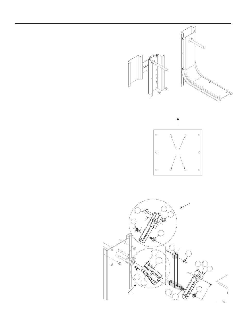
5. Assemble the linkage.
Parts needed for dampers with
1
/
2
in. shafts:
(Qty. 3)
1
/
2
in. crankarms (item 7)
(Qty. 3)
5
/
16
in. - 18 x 1
1
/
2
in. bolts (item 8)
(Qty. 3)
5
/
16
in. - 18 spinlock nuts (item 9)
(Qty. 1)
1
/
4
in. x
1
/
2
in. knurl pin (item 19)
(Qty. 1) Drive link (item 15)
(Qty. 1) Linkage adjustment pin (item 13)
(Qty. 2)
1
/
4
in. E-ring (item 14)
(Qty. 1)
1
/
4
- 20 spinlock nuts (item 6)
Parts needed for dampers with 1 in. shafts:
(Qty. 1) 1 in. crankarm (item 10)
(Qty. 1)
3
/
8
in. - 16 x 2
1
/
2
in. bolt (item 11)
(Qty. 1)
3
/
8
in. - 16 spinlock nut (item 12)
(Qty. 2) Linkage adjustment pin (item 13)
(Qty. 1)
1
/
2
in. crankarms (item 7)
(Qty. 1)
5
/
16
in. - 18 x 1
1
/
2
in. bolts (item 8)
(Qty. 1)
5
/
16
in. - 18 spinlock nuts (item 9)
(Qty. 1) Drive link (item 15)
(Qty. 2)
1
/
4
in. E-ring (item 14)
(Qty. 2)
1
/
4
- 20 spinlock nuts (item 6)
Dampers with a jackshaft
1. Mount the anchor bracket onto the jackshaft bracket
with (4)
1
/
4
-20 x
1
/
2
in. thread cutting screws (Item 17) as
shown in Figure 1a.
2. Attach anchor bracket to sleeve with (2) #14 x
3
/
4
HWH
Tek screws (Item 20). Position the Tek screws as far
down the sleeve as possible.
3. Mount the mounting bracket to the anchor bracket using
(6) #14 x
3
/
4
HWH Tek screws (Item 20).
Dampers without a jackshaft (Shaft Extension)
1. Mount the mounting bracket spanning across the
damper frame flanges, positioned over the control
shaft as shown in Figure 1b. The damper shaft must be
centered in the mounting bracket. Fasten to the damper
frame with (4) #14 x
3
/
4
HWH Tek screws (Item 20) or
equal, supplied by others. Be sure not to run the screws
into the damper linkage, which is between the flanges.
2. Fasten the mounting plate (Item 3) to the mounting
bracket (Item 2) using (4)
1
/
4
in. - 20 x
1
/
2
in. thread studs
(Item 4) and (4)
1
/
4
in. -20 spinlock nuts (Item 6) through
the matching four hole pattern on the mounting bracket
labeled A on the illustration.
3. If the damper has a
1
/
2
in. diameter damper shaft, mount
the ball bearing into the mounting bracket with two #10
Tek screws (Item 20). The Tek screws are required to
keep the thrust forces from pushing the bearing out
of the mounting bracket. If the damper shaft is 1 in.
diameter, then no ball bearing is required.
4. Mount the actuator to the mounting plate in the
corresponding holes using (3)
1
/
4
- 20 x
3
/
4
in. thread
cutting screws (Item 5). Note: the actuator must be
mounted with the shaft in the horizontal position.
Instructions
Mounting Plate
A
6d
6c
Steps 6a,b for dampers
with 1 in. shafts
(substitute these parts in
place of 7,8,9 &19)
Steps 6a,b
for dampers with
1
Ú
2
in. shafts.
Figure 1b - Orientation of
Mounting Bracket for a
directly driven damper
Figure 1a - Orientation of
Stand Off Bracket for a
jackshaft driven damper
Damper
9
7
8
19
14
13
6
8 7
9
14
15
13
12
10
6
11
3 in.
2
14
in.
/