Greenheck MA6 Series (455410) User Manual
Page 3
5a. Assemble the shaft crankarms.
For dampers with
1
/
2
in. shafts:
The crankarms must be placed as mirror images of
each other, meaning the like sides face each other. The
bolts and nuts are to be positioned as in the exploded
view to the left.
For dampers with 1 in. shafts:
Replace Items 7, 8, 9, & 19 with Items 6, 10, 11, 12, & 13
as shown above in the encircled exploded view. There
is only one crankarm, but the fail positions are still set
up the same.
5b. For dampers with
1
/
2
in. shafts:
Insert the knurl pin through both of the small holes in
the crankarms and tap it into place using a hammer.
For dampers with 1 in. shafts:
Insert the linkage adjustment pin (item 13) into the
crankarm slot. Position it 3 in. from the center of the
damper shaft hole and fasten with a
1
/
4
-20 spinlock nut
(see encircled diagram).
5c. Attach the drive link (item 15) to the damper shaft
crankarm(s)
For dampers with
1
/
2
in. shafts:
Insert the knurl pin through one of the drive link holes.
Fasten with an E-ring.
For dampers with 1 in. shafts:
Insert the linkage adjustment pin (item 13) through one
of the drive link holes. Fasten with an E-ring.
5d. Attach the drive link to the actuator crankarm with
the linkage adjustment pin, a spinlock nut and an E-
ring. Set the linkage adjustment pin at 2
1
/
4
in. on the
crankarm and secure it there with the spinlock nut.
Fasten the other end through the empty drive link hole
with the E-ring.
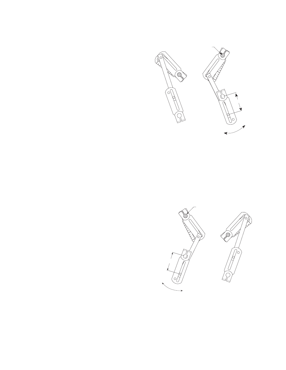
6. Note the damper shaft rotation for fail direction and
orient the linkage appropriately as shown in the
linkage illustration. The damper linkage is now in its fail
position. Position the damper blades to their proper
position (open or closed). Tighten the bolts.
7. Orient the actuator crankarm so that it will rotate
through the full stroke of the actuator with the shaft
crankarms rotating only 90 degrees without power.
Adjust the position as necessary. Tighten all of the
crankarms.
Power Position
Fail Position
Damper Shaft
Power
Return
2
1/4
in.
Power Position
Fail Position
Power
Return
Damper Shaft
2
1
⁄
4
in.
Clockwise to Fail Position
Counterclockwise to Fail Position