Check operation - vav units (optional), Modulating, Speed vfd motor – Greenheck DG/DGX Pilot Ignition (470651_IOM) User Manual
Page 22: Variable volume operation, Burner bypass damper (optional)
Burner Bypass Damper
Burner
Bypass Damper
WARNING
The burner bypass damper is set-up at the factory.
The weights should not be adjusted in the field. The
damper may not fully close during minimum outside
air mode.
70
65
75
80
85
90
60
55
(OPTIONAL)
BLOWER
DIRTY FIL TERS
MAIN V AL VES
EXHAUST
SUPPL Y
HEA T
(OPTIONAL)
PHOTOHELIC
Building
Pressure Control
NOTE
Blower Start-Up, Steps 1-5 should be performed
before the blower is run.
NOTE
For maintenance issues associated with variable
frequency drives, consult the drive’s manual
supplied with the unit. The drives are programmed
at the factory and should not need any adjustment
during installation and start-up. For kitchen
applications, the drive may be located in the kitchen
or in the unit.
Modulating
Potentiometer Control - a variable frequency drive
is controlled by input from a remote
speed selector (potentiometer).
This unit allows easy manual
adjustment of make-up air
volumes. To test potentiometer
operation, turn the potentiometer
to the two extremes. With variable
volume, make sure the fan goes to
maximum and minimum speed.
When the potentiometer is at 0, the
fan speed will be at its minimum.
When the potentiometer is at 100,
the fan will be at its maximum
speed.
2-Speed VFD Motor
A variable frequency drive (VFD) is used on a single
speed motor to control air volumes. The VFD is
factory-programmed for 2 speed operation. It can be
switched to low or high speed from a remote control
panel. Turn the fan speed switch on the remote control
panel to each position and confirm that the fan speed
adjusts accordingly.
Variable Volume Operation
The variable volume option is recommended when
a building’s exhaust volume may vary. This option
enables the make-up air volume to track with the
exhaust volume, providing only the amount of make-
up air required. Control strategies include 2-speed
VFD motors and modulating blowers. Before the unit
is left in service, the variable volume control system
should be tested.
EXHAUST
(OPTIONAL)
(OPTIONAL)
55
60
65
70
75
80
85
90
SUPPLY
HEAT
DIRTY FILTERS
MAIN VALVES
BLOWERS
Potentiometer
Control
Check Operation - VAV Units
(optional)
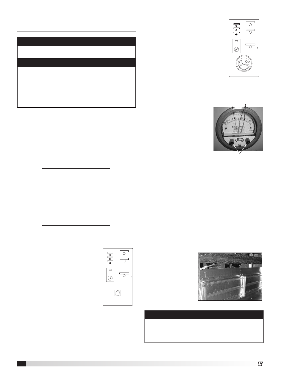
Photohelic Gauge
Pressure
Indicating
Needle
Pressure
Setting
Needles
Pressure Setting Knobs
Building Pressure Control -
a variable frequency drive is
controlled according to input from
a pressure sensing device.
Turn both knobs to the upper
most pressure setting. You may
have to remove the outdoor
pressure tap tubing. VAV systems
should go to maximum speed. Set
both knobs at the lowest setting
and the VAV systems should go to
minimum speed.
Reset the correct pressure
limits before starting the unit.
This picture depicts a typical
photohelic setting. Typical
settings are 0.0 inch wc for
the lower pressure setting
and 0.10 inch wc for the
upper pressure setting. The
needle indicates a negative
building pressure. During
correct operation, the
indicating needle will remain
between or near the setting
needles.
External Signal - a variable frequency drive is
controlled according to input from an external
2-10 VDC or 4-20 mA signal (by others).
A 2 VDC or 4 mA signal will send the blower to low
speed. The blower will go to maximum speed with a
10 VDC or 20 mA signal.
Variable Kitchen Control - a variable frequency drive
is controlled by input from a remote speed control.
This unit allows automatic adjustment of make-up air
volumes based on varying cooking loads.
Burner Bypass Damper (optional)
The self-adjusting burner bypass damper is a
device used in variable volume units. Its function is
to maintain proper
combustion by
providing a constant
airflow over the
burner when outside
air volumes are
changed. It is located
underneath the
burner as shown in
the picture.
Model DG / DGX Pilot Ignition Make-Up Air
22
®