Switch – Greenheck S73 Series User Manual
Page 11
f
ield
install
.
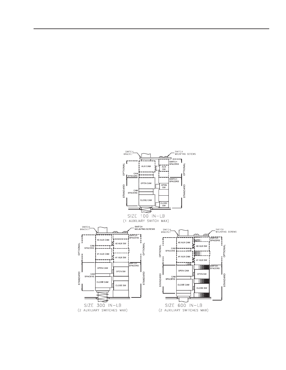
Of
auxiliary
switch (
es
)
The maximum allowable auxiliary switch configuration is
shown in the illustrations below for each size of actuator.
a
uxiliary
s
witch
K
it
c
Onsists
O
f
:
1. Switch with flying leads
2. Switch spacers
3. Cam with set screw
4. Cam spacers
5. Pan head screw, phillips drive
t
OOls
r
equired
For terminal wiring Screwdriver, 3/16” flat tip blade
i
nstallatiOn
P
rOcedure
:
For switch mounting Screwdriver, No. 1 phillips
1. Remove switch mounting screws & discard
2. Remove switch bracket & retain for use later
3. Install auxiliary cam(s) and spacers as shown
4. Install auxiliary switch(es) and spacers as shown
5. Reinstall switch bracket
6. Install longer switch mounting screws from kit
7. Connect switch wiring to terminal strip per wiring
diagram
8. Adjust cams as required
BRAY Series 73 Electric Actuator
Operation and Maintenance Manual
9