User's manual, Cmos clear, Atx serial ports – Hypertherm SuperMicro 370SBA 533Mhz User Manual
Page 36: Wake-on-lan, Fan connectors
2-6
SUPER 370SBA/370SBM/370SLA/370SLM
User's Manual
Table 2-11
ATX Serial Ports Pin Definitions
Pin Number
Definition
1
D C D
2
D S R
3
Serial In
4
R T S
5
Serial Out
Pin Number
Definition
6
C T S
7
D T R
8
RI
9
Ground
10
N C
J20
J21
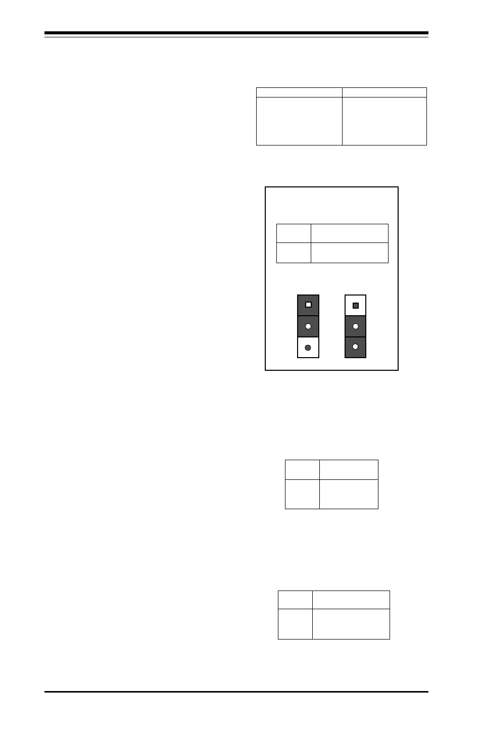
Table 2-12
CMOS Clear Pin Definitions
for Number JBT1
Jumper
Position
1-2
2-3
Definition
Normal
C M O S C l e a r
Position
1-2
Position
2-3
Normal
CMOS Clear
Table 2-14
Fan Connectors Pin
Definitions for JT1, JT2, JT3
Pin
Number
1
2
3
Definition
Ground (black)
+12V (red)
Tachometer
* Caution: These fan connectors
are DC direct.
CMOS Clear
Refer to Table 2-12 for instructions
on how to clear the CMOS. For an
ATX power supply, you need to
completely shut down the sys-
tem, then use JBT1 to clear the
CMOS. Do not use the PW_ON
connector to clear the CMOS. A
second way of resetting the CMOS
contents is by depressing the <Ins>
key, then turning on the system
power. Release the key when the
power comes on.
ATX Serial Ports
ATX serial port COM1 is located on
J20 and serial port COM2 is located
on J21. See Table 2-11 for pin defi-
nitions.
Pin
N u m b e r
1
2
3
Definition
+5V Standby
Ground
W a k e u p
Table 2-13
Wake-on-LAN Pin
Definition located at
W O L
Wake-on-LAN
The Wake-on-LAN connector is lo-
cated on WOL. Refer to Table 2-13
for pin definitions.
Fan Connectors*
The thermal/overheat fan is located
on JT3. The CPU fans are located
on JT1 and JT2. Refer to Table
2-14 for pin definitions.