Basic controls, basic displays, weld data, Welding dynamics control, Selections for main controls – Kemppi ProMXE User Manual
Page 13
KEMPPI PRO EVOLUTION, MXE / 0547 – 13
© KEMPPI OY
22
21
20
19
18
17
23
26
25
24
27
3.3.1. 1-MIG or PulsedMIG synergic curve is selected as follows
a) Select 1-MIG or PulsedMIG.
b) Select material group. You get from the material group in question the curve with which
was started last. If the selected material is not the right one, you can browse materials in the
material group by re-pressing the material group selection key.
c) Select shielding gas. Only gas selections possible for the material in question are displayed.
d) Select wire diameter. Only diameters possible for the filler wire/gas selection in question
can be selected. The unit remembers (MEMORY) last selections from each material group
(material, gas, wire diameter) separately at 1-MIG and PulsedMIG.
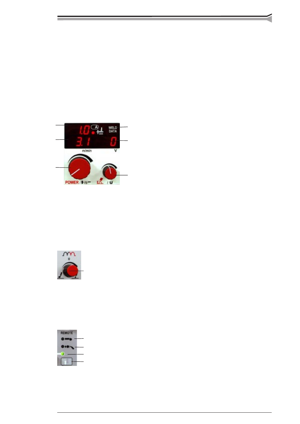
3.4. BASIC CONTROLS, BASIC DISPLAYS, WELD DATA
17. Control for wire feed speed in MIG/MAG, welding
power in 1-MIG and PulsedMIG, and welding cur-
rent in MMA.
18. Display for wire feed speed or MMA current.
19. Informative plate thickness display in 1-MIG and
PulsedMIG for horizontal vertical fillet weld. During
welding true welding current display.
20. Control for welding voltage (MIG/MAG), or arc
length (1-MIG and Pulsed MIG).
21. Display of welding voltage set value with MIG/MAG and 1-MIG. Set value display for arc
length with Pulsed-MIG, range -9...0...9. During welding pole voltage of power source is
displayed. Display is also used as display of welding dynamics control, -9...0...9.
22. Pressing the WELD DATA key restores to displays those values of wire feed speed, welding
current and welding voltage which were used when welding was stopped.
3.5. WELDING DYNAMICS CONTROL
23. Control for MIG/MAG, 1-MIG and MMA welding dynamics. Control
value -9...0...9 is displayed in display 21. Welding dynamics control
influences welding stability and spatter amount. Zero position is recom-
mended as basic setting. Values -9...-1, softer arc in order to reduce spatter
amount. Values 1...9, harder arc in order to increase stability, and when
using 100 % CO
2
shielding gas in steel welding.
3.6. SELECTIONS FOR MAIN CONTROLS
24. Local control, main controls are made from panel potentiometers 17 and 20.
25. Gun control, wire feed speed or welding power controls are made from
control unit RMT10, which is mounted to PMT MIG gun. Welding voltage
or arc length controls are made from panel potentiometer 20.
26. Remote control, main controls are made from control unit R20 connected to
main wire feeder or from PROMIG 100 sub-feeder.
27. Control selection key.
Note! You cannot select remote control mode or gun remote control mode if the
control unit is not connected to the welding equipment.