Kleenmaid CM01X User Manual
Page 17
17
17
17
17
17
AMC3
2. Fix the 4 brackets "A" to the 4 corners of
the cabinet opening, using the appropri-
ate screws (Fig. 3).
The horizontal movement of the nut allows
any width tolerance of the cabinet to be
offset.
3. Fix the 2 angular brackets "B" to the ma-
chine (Fig. 3). The 2 vertical holes on the
brackets allow the height of the machine
to be levelled and aligned.
4. Connect the machine to the electricity sup-
ply, observing the current safety regula-
tions.
Important: The current plug must be
reachable after the installation of the
machine.
5. Place the machine in the centre of the cabi-
net, taking care that the horizontal side of
the 2 angular brackets "B" are slotted into
the appropriate holes on the brackets "A"
(Fig. 3).
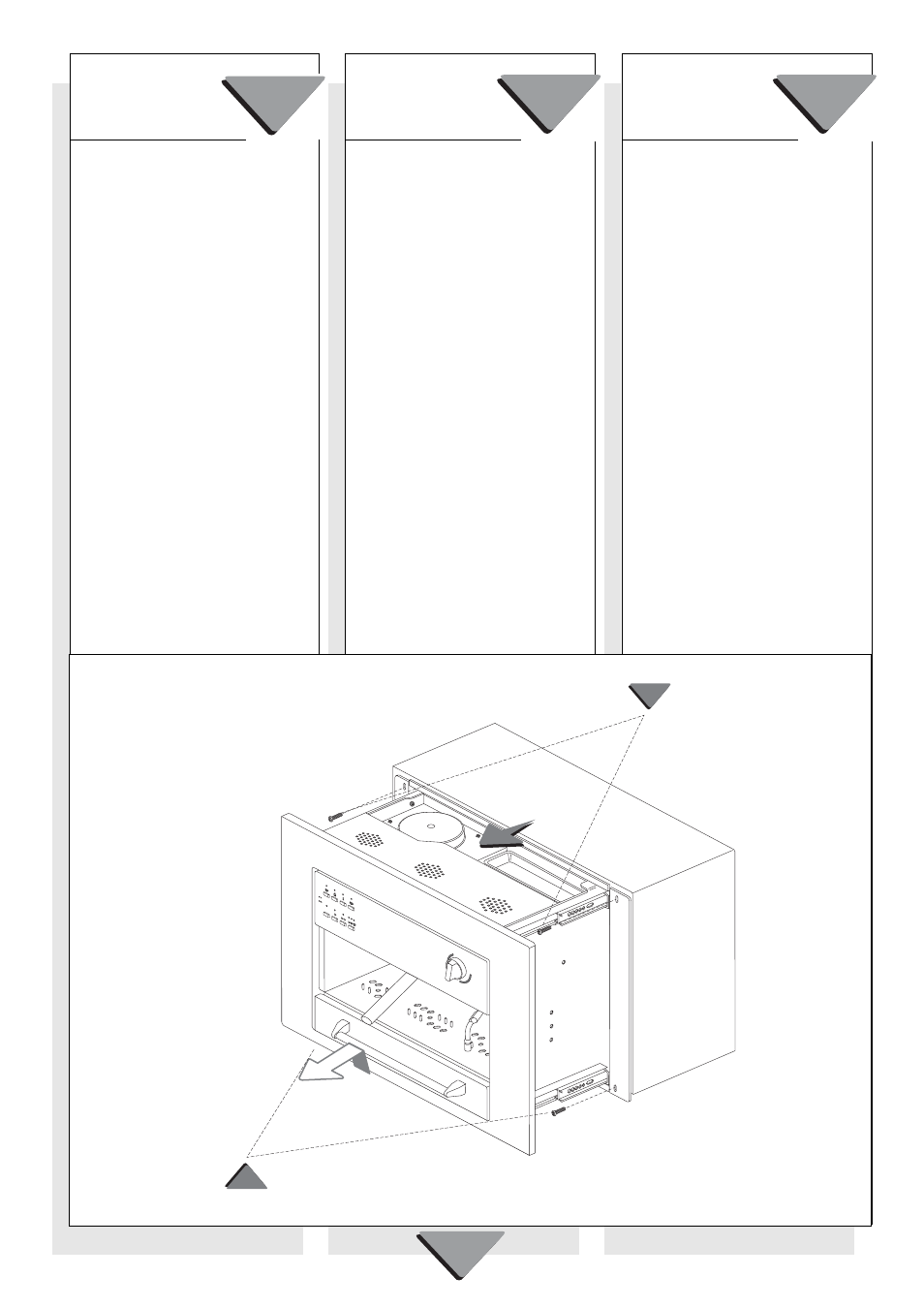
6. Open the machine by lifting the handle and
pulling outwards, taking care not to pull it
out of the cabinet (Fig. 4).
7. Secure the machine using the appropri-
ate screws "C" (Fig. 4).
8. Close the machine.
The manufacturer declines any responsi-
bility for persons or property and for the
incorrect operation of the machine if the
above instructions are not observed in
full.
2. Sujetar con los correspondientes tornillos,
las 4 bridas "A" (Fig.3) en los 4 ángulos
de la abertura del mueble.
El movimiento horizontal de la tuerca per-
mite compensar las eventuales tolerancias
del mueble en anchura.
3. Sujetar los 2 angulares "B" (fig.3) a la
máquina. Los dos orificios de las bridas
nos permiten nivelar y alinear la altura de
la máquina.
4. Conectar la máquina a la red eléctrica res-
petando las leyes existentes.
Cuidado: El enchufe debe encontrar-
se en lugar accesible después de su
instalación.
5. Colocar la máquina centrándola en el
mueble y teniendo cuidado de que el lado
horizontal de los dos angulares "B" se
introduzcan bien en el sitio (con forma de
ojal) de las bridas "A" (fig.3).
6. Abrir la máquina levantándo la manilla y
tirando hacia si teniendo cuidado de que
no se salga del mueble (fig.4)
7. Sujetar la máquina con los tornillos "C"
(fig.4).
8. Cerrar la máquina.
El fabricante declina toda responsabilidad
por daños causados a personas o cosas,
o al correcto funcionamiento de la máqui-
na si no se respeta cuanto indicado mas
arriba.
2. Maak met de bijgevoegde schroeven, de
4 "A" bouten (Fig.3) vast aan de 4 hoek-
punten van de kastopening.
De horizontale beweging van de moer
compenseert de mogelijke breedte-
afwijkingen van de kast.
3. Monteer de 2 "B" hoeken (fig.3) aan het
toestel. De 2 vertikale gaten op de bouten
maken een nivellering en uitlijning in de
hoogte mogelijk van het toestel .
4. Maak de elektrische aansluiting volgens
de geldende veiligheidsvoorschriften.
Belangrijk: De stekker moet ook bereik-
baar zijn nà de installatie van het ap-
paraat.
5. Centreer het toestel in de opening van de
kast en zorg ervoor dat de horizontale kant
van de 2 "B" hoekpunten in de voorziene
opening (gat) past van de "A" bouten
(fig.3).
6. Open het toestel door het handvat omhoog
te heffen, daarna naar zich toe trekken; let
op dat het toestel niet uit de kast valt (fig.4)
7. Blokkeer de machine met de voorziene "C"
schroeven (fig.4).
8. Sluit de machine.
De fabrikant is niet verantwoordelijk voor
schade veroorzaakt aan personen of voor-
werpen, ook aan het toestel zelf door het
niet naleven van de hierboven vermelde
aanwijzingen.
ESP
ESP
ESP
ESP
ESPAÑOL
AÑOL
AÑOL
AÑOL
AÑOL
ENGLISH
ENGLISH
ENGLISH
ENGLISH
ENGLISH
Fig. 4
Fig. 4
Fig. 4
Fig. 4
Fig. 4
ON/OF
F
ON/OFF
C
C
NEDERLANDS
NEDERLANDS
NEDERLANDS
NEDERLANDS
NEDERLANDS