Setting “a” = 1/2” material, Setting “b” = 3/4” material, Setting “c” = 1-1/2” materia l – Kreg DK1100 Single-Spindle Electric Pocket-Hole Machine User Manual
Page 12
R
DK1100 FE / DK3100
11
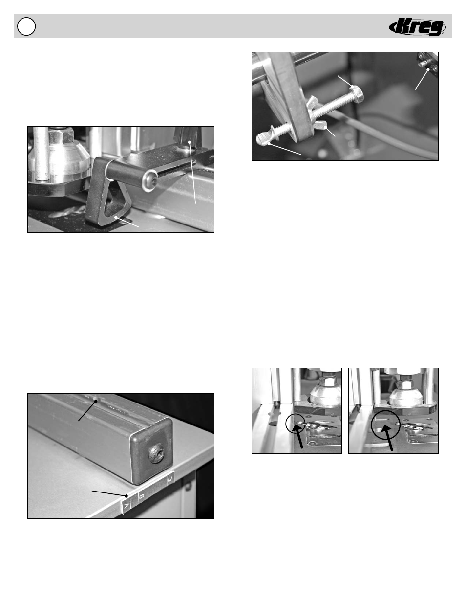
B) Adjusting the Drill Bit Depth Stop
A Drill Bit Depth Stop is provided to stop the Drill Bit forward
motion and control the Drill Feed Cylinder cycle. When the
head of the Drill Bit Depth Stop fully engages the Depth
Control Switch the forward motion of the Drill Bit is stopped
and reversed to complete the drilling cycle. Before adjusting
the Drill Bit Depth Stop make certain your machine is
DISCONNECTED from the AIR SUPPLY and/or ELECTRICAL
SUPPLY. Cycle the machine via the foot switch several
times to remove air from the system. Without an air supply
or electrical supply you can be certain the machine will not
accidentally engage while you are performing maintenance.
Step 1: Loosen the Lock Nut on the Depth Control Adjuster.
Adjust the Depth Control Adjuster the approximate
position.
Step 2: Push the Drill Bit Drive Assembly forward until the
Drill Bit pilot point is slightly away from the Fence. For
1/2” and 3/4” material, push your drill bit up to be
approximately 1/8” from the tip to the edge of the
fence.
For 1-1/2” material, push your drill bit up to be
approximately 1” from the tip to the edge of the fence.
Step 3: Adjust the Drill Depth Control Adjuster until the Head
fully depresses the plunger on the Depth Control
Switch.
Step 4: Tighten the Lock Nut to lock the Depth Control
Adjuster in position.
Step 5: Pull the Drill Bit Drive Assembly back into the
resting
position.
Lock Nut
Depth Control
Switch
Head
Depth Control Adjuster
A) Adjusting the Fence Setting
The Fence can be adjusted to align the pocket hole to the center
of material of different thicknesses. When adjusting the Fence
make sure that the Fence remains perpendicular to the Guide
Plate. A Reference Scale has been provided to approximate the
fence setting for 1/2”, 3/4”, and 1-1/2” thick material. These
correspond to the “A”, “B”, and “C” lines on the Reference Scale.
Step 1: Loosen the (4) Socket-head Cap Screws contained
below the surface of the Fence.
Step 2: Align the Fence perpendicular to the Guide Plate for
the setting that corresponds to the material thickness.
Step 3: Tighten the (4) Socket-head Cap Screws to lock the
Fence into position.
Swing Stops
Two Swing Stops are provided to assist in drilling pocket holes
in the same location on multiple work pieces of the same
dimension. When the Swing Stop is not used, it will pivot out
of the way to allow the work piece to slide underneath and rest
against the fence. To change the location of the Swing Stop
simply loosen the Knob, move to the new location and tighten
the Knob to lock the Swing Stop in position.
Swing Stop
Knob
NOTE: Always remember as your drill bit gets shorter
from sharpening, that you will need to compensate for
that distance too.
Setting “A” = 1/2” Material
*
Setting “B” = 3/4” Material
*
Setting “C” = 1-1/2” Material
*
*Approximate fence setting.
Reference Scale
Access to Socket-
Head Cap Screws
Adjusting the Machine For Stock Thickness
Shown for use with 1/2 & 3/4” Settings.
Shown for use with 1-1/2” Setting.