Appendix b serial console port interfaces – Legrand SPDU8-1U User Manual User Manual
Page 21
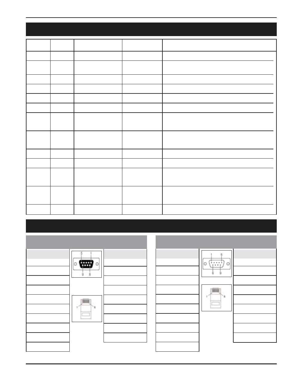
RS-232 — DB9 FEMALE
RJ45 (8-PIN)
RJ45 (8-PIN)
RS-232 — DB9 MALE
18
APPENDIX B SERIAL CONSOLE PORT INTERFACES
PIN #
NAME
LONG NAME
DIRECTION
DESCRIPTION
1
DCD
Data Carrier Detect
<<<
Raised when an carrier communication is established.
2
TD
Transmitting Data
>>>
Serial data stream sent to the DTE device.
Same note as above apply.
3
RD
Receive Data
<<<
Receives serial data stream.
4
DSR
Open
<<<
Not connected.
5 GND
Signal
Ground
6
DTR
Terminal Ready
>>>
Indication of serial port activated.
7
CTS
Clear To Send
<<<
When hardware flow control is enabled, if this signal is
raised, an external device can send data to Local
Master Port.
8
RTS
Request To Send
>>>
When hardware flow control is enabled, this signal is
raised by the Local Master Port when it is ready to
receive new data from an external device.
9
Open
Open
6
Open
<<<
Not connected.
8
CTS
Clear To Send
<<<
When hardware flow control is enabled, if this signal is
raised, an external device can send data to Local
Master Port.
7
RTS
Request To Send
>>>
When hardware flow control is enabled, this signal is
raised by the Local Master Port when it is ready to
receive new data from an external device.
9
Open
Open
APPENDIX C RS-232 TO RJ45 CONVERSION CABLES
PIN #
SIGNAL
1
DCD
2
TxD
3
RxD
4
DSR
5
GND
6
DTR
7
CTS
8
RTS
9
–
PIN #
SIGNAL
1
DSR
2
RTS
3
GND
4
TxD
5
RxD
6
DCD
7
CTS
8
DTR
DB-9 F
R S - 2 3 2 — R J 4 5 ( 8 - P I N )
C-RJ45-DB9F-4, RJ-45 to RS232 (Female, DCE) cable, 4’
PIN #
SIGNAL
1
DCD
2
RxD
3
TxD
4
DTR
5
GND
6
DSR
7
RTS
8
CTS
9
–
PIN #
SIGNAL
1
DSR
2
RTS
3
GND
4
TxD
5
RxD
6
DCD
7
CTS
8
DTR
R S - 2 3 2 — R J 4 5 ( 8 - P I N )
C-RJ45-DB9M-4, RJ-45 to RS232 (Male, DTE) cable, 4’
8
8
DB-9 M
- SPDU16-2U User Manual SPDU20-0U User Manual WKD ProSeries Underfloor Duct Opening Reducer 880CM1-1 880CM2-1 880CM3-1 880CS1-1 880CS1-NA 880CS2-1 880CS2-NA 880CS3-1 880CS3-NA 880M1 880M2 880M3 880S1 880S2 880S3 828MAAP PCIQ PDU-TS1 Temperature Sensor WKD ProSeries Underfloor Duct Nonmetallic Fittings 525 Series Service Fittings RC7AP AMD8 Abandonment Plugs AV3ATCBK AV3ATCGY AV3ATCVY AV3ATCAL AV3ATCBS AV3ATCAA AV3ATCAB CCWB Series Wall Boxes 24DWND 24DWNR 881 Series Ratchet-Pro Multi-Service Round Floor Box