Basic connections, English, Connecting audio components – Marantz SR4023 User Manual
Page 11: Connecting video components, Cd player cd recorder tape deck turn table
8
BASIC
OPERA
TION
ADV
ANCED
CONNECTIONS
ADV
ANCED
OPERA
TION
TROUBLESHOOTING
OTHERS
NAMES AND
FUNCTIONS
BASIC
CONNECTIONS
ENGLISH
BASIC CONNECTIONS
CONNECTING AUDIO COMPONENTS
AUX
AUX
DSS
DSS
DVD
DVD
VCR
VCR
IN
IN
IN
IN
OUT
OUT
IN
IN
OUT
OUT
DSS
DSS
DVD
DVD
VIDEO
VIDEO
VCR
VCR
AUX
AUX
MONITOR
MONITOR
IN
IN
IN
IN
IN
IN
IN
IN
IN
IN
IN
IN
IN
IN
OUT
OUT
OUT
OUT
IN
IN
IN
IN
OUT
OUT
PHONO
PHONO
GND
GND
L
L
R
R
CD
CD
RECORDER 2
RECORDER 2
(
(TAPE
TAPE)
)
RECORDER 1
RECORDER 1
(
(CD-R
CD-R)
)
AUDIO
AUDIO
RS-232C
GND
GND
AM
AM
FM
FM (
(75
75
Ω
Ω))
ANTENNA
ANTENNA
FLASHER
FLASHER
IN
IN
IN
IN
PHONO
PHONO
GND
GND
L
L
R
R
IN
IN
OUT
OUT
OUT
OUT
IN
IN
IN
IN
CD
CD
RECORDER 2
RECORDER 2
(
(TAPE
TAPE)
)
RECORDER 1
RECORDER 1
(
(CD-R
CD-R)
)
AUDIO
AUDIO
L R
PHONO
OUT
L R
ANALOG
OUT
L R
LINE
OUT
L R
LINE
IN
L R
ANALOG
OUT
L R
ANALOG
IN
L
R
L
R
L
R
L
R
L
R
L
R
L
R
L
R
L
R
L
R
L
R
L
R
CD player
CD recorder
Tape Deck
Turn table
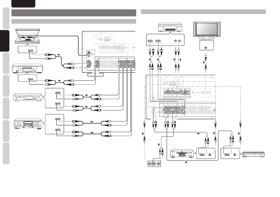
The output audio signal from the RECORDER 1 OUT jack and the RECORDER 2 OUT jack is the same signal
which is currently selected.
Caution:
• Do not connect this unit and other components to mains power until all connections between components have been
completed.
Notes:
• Insert all plugs and connectors securely. Incomplete connections may make noise.
• Be sure to connect the left and right channels properly.
Red connectors are for the R (right) channel, and white connectors are for the L (left) channel.
• Be sure to connect input and output properly.
• Refer to the instructions for each component that is connected to this unit.
• Do not bind audio/video connection cables with power cords and speaker cables this will result in generating a hum
or other noise.
CONNECTING VIDEO COMPONENTS
AUX
AUX
DSS
DSS
DVD
DVD
VCR
VCR
IN
IN
IN
IN
OUT
OUT
IN
IN
OUT
OUT
DSS
DSS
DVD
DVD
VIDEO
VIDEO
VCR
VCR
AUX
AUX
MONITOR
MONITOR
IN
IN
IN
IN
IN
IN
IN
IN
IN
IN
IN
IN
IN
IN
OUT
OUT
OUT
OUT
IN
IN
IN
IN
OUT
OUT
PHONO
PHONO
GND
GND
L
L
R
R
SUB
SUB
WOOFER
WOOFER
PRE
PRE
OUT
OUT
CD
CD
PRE
PRE
OUT
OUT
RECORDER 2
RECORDER 2
(
(TAPE
TAPE)
)
MAIN
MAIN
IN
IN
RECORDER 1
RECORDER 1
(
(CD-R
CD-R)
)
AUDIO
AUDIO
RS-232C
RS-232C
GND
GND
AM
AM
FM
FM (
(75
75
Ω
Ω))
ANTENNA
ANTENNA
FLASHER
FLASHER
IN
IN
AUX
AUX
DSS
DSS
DVD
DVD
VCR
VCR
IN
IN
IN
IN
OUT
OUT
IN
IN
OUT
OUT
DSS
DSS
DVD
DVD
VIDEO
VIDEO
VCR
VCR
AUX
AUX
MONITOR
MONITOR
IN
IN
IN
IN
IN
IN
IN
IN
IN
IN
OUT
OUT
AUDIO
AUDIO
VIDEO
IN
CVBS
L R
AUDIO
OUT
VIDEO
OUT
L R
AUDIO
OUT
AUDIO
IN
L R
VIDEO
OUT IN
L R
AUDIO
OUT
VIDEO
OUT
L R
L R
L R
L
R
L
R
L R
L R
L R
L R
L R
OUT
OUT
L
VIDEO
R
VCR
Monitor
DVD player
Satellite tuner
VIDEO camera etc..
Notes:
• Insert all plugs and connectors securely. Incomplete connections will result in the generation of noise.
• Be sure to connect the left and right channels properly.
Red connectors are used for the R (right) channel, and white connectors are used for L (left) channel.
• Be sure to connect input and output of video signal properly.