English connecting the remote control jacks, The setting “ir=enable” is shown on the fl display – Marantz SR4023 User Manual
Page 17
14
BASIC
CONNECTIONS
BASIC
OPERA
TION
ADV
ANCED
OPERA
TION
TROUBLESHOOTING
OTHERS
NAMES AND
FUNCTIONS
ADV
ANCED
CONNECTIONS
ENGLISH
CONNECTING THE REMOTE CONTROL JACKS
REMOTE CONTROL
REMOTE CONTROL
AUX
AUX
DSS
DSS
DVD
DVD
VCR
VCR
IN
IN
IN
IN
OUT
OUT
IN
IN
OUT
OUT
DSS
DSS
DVD
DVD
VIDEO
VIDEO
VCR
VCR
AUX
AUX
MONITOR
MONITOR
IN
IN
IN
IN
IN
IN
IN
IN
IN
IN
IN
IN
IN
IN
OUT
OUT
OUT
OUT
IN
IN
IN
IN
OUT
OUT
PHONO
PHONO
GND
GND
L
L
R
R
SUB
SUB
WOOFER
WOOFER
PRE
PRE
OUT
OUT
CD
CD
PRE
PRE
OUT
OUT
RECORDER 2
RECORDER 2
(
(TAPE
TAPE)
)
MAIN
MAIN
IN
IN
RECORDER 1
RECORDER 1
(
(CD-R
CD-R)
)
AUDIO
AUDIO
RS-232C
RS-232C
R
R
R
R
L
L
L
L
AC IN
AC IN
CLASS 2 WIRING
CLASS 2 WIRING
GND
GND
AM
AM
FM
FM (
(75
75
Ω
Ω))
ANTENNA
ANTENNA
MODEL NO. SR4023
MODEL NO. SR4023
IN
IN
OUT
OUT
A
A
SYSTEM
SYSTEM
B
B
SPEAKER SYSTEMS
SPEAKER SYSTEMS
SYSTEM
SYSTEM
FLASHER
FLASHER
IN
IN
UNSWITCHED
UNSWITCHED
1.25A 150W
1.25A 150W
AC OUTLETS
AC OUTLETS
120V 60Hz
120V 60Hz
SWITCHED
SWITCHED
1.25A 150W
1.25A 150W
REMOTE CONTROL
REMOTE CONTROL
OUT
OUT
REMOTE
CONTROL
REMOTE
CONTROL
REMOTE
CONTROL
IN
OUT
IN
OUT
IN
OUT
EXTERNAL INTERNAL
EXTERNAL INTERNAL
EXTERNAL INTERNAL
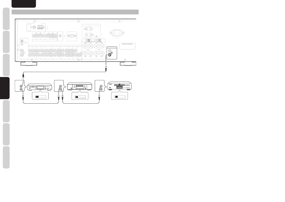
CD player
CD recorder
DVD player
q
You can control other Marantz products through
this unit with the remote control by connecting the
REMOTE CONTROL terminals on each unit.
The signal transmitted from the remote control is
received by the remote sensor on this unit. Then the
signal is sent to the connected device through this
terminal. Therefore you only need to aim the remote
at one unit. Also, if a Marantz power amplifi er (some
models excluded) is connected to one of these
terminals, the power amplifier’s, power switch is
synchronized with this unit’s power switch.
Set the REMOTE CONTROL SWITCH on the units,
other than the main unit to EXT.(EXTERNAL) for this
feature.
w
Whenever external infrared sensors or similar devices
are connected to RC-5 IN of the SR4023, be sure to
always disable operation of the infrared sensor on the
main unit by using the following procedure.
1.
Hold down the S-DIRECT button and BAND
button on the front panel at the same time for 3
seconds.
2.
The setting “IR=ENABLE” is shown on the FL
DISPLAY.
3.
Press
TUNING/PRESET
3
or
4
button to
change this to “IR=DISABLE”.
4.
Press
the
MUTE button. Once this setting is
made, the infrared sensor on the main unit is
disabled.
Note:
Be sure to set to “IR=ENABLE” when external
infrared sensors or similar devices are not connected.
Otherwise, the main unit will be unable to receive
remote control commands.
5.
To restore the original setting, perform steps 1
to 4 to set to “IR=ENABLE”.