Installation, Wiring, Installing the log set – Montigo MW34 DV User Manual
Page 12: Gas control and pilot wiring, Wiring for the optional fan and blower kits
Page 12 of 21
W3400 Gas Fireplace
Installation
Wiring
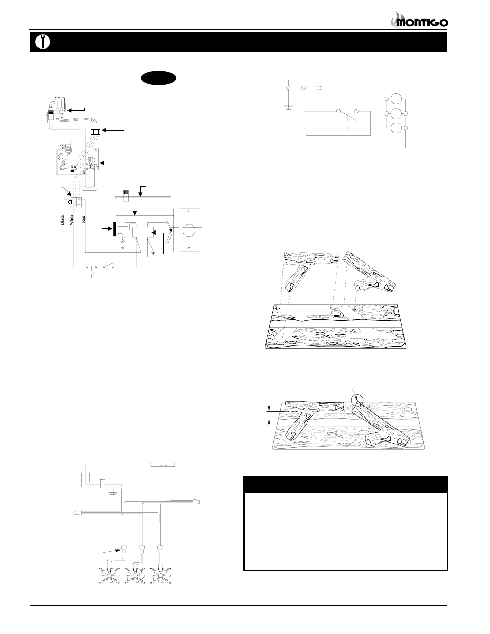
Figure 21b. Wiring schematic for optional fan kit.
Figure 21a. Wiring for optional air circulating fan kit.
Installing the Log Set
The W3400 is supplied with four (4) ceramic fibre logs. Logs "A" and
"B" are factory-installed on the log rest. To install the two small logs
("C" and "D"), simply place them onto their mating positions as shown
in figure 24a below. When log set is installed it should look like figure
24b.
Figure 22a. Log placement.
Figure 22b. Completed log installation.
NOTES
:
If logs are not placed properly, excessive sooting will result.
If handling or vacuuming the logs, do not attempt to move
the two large logs. They are extremely fragile, and will break
easily.
The surface of the logs will crack due to the heat from the
flames. This is a normal occurance.
Gas Control and Pilot Wiring
W3410
Honeywell (Q3450)
Pilot Assembly
Pilot Electrical
Harness Connector
Honeywell Gas
Control (SV9501M)
Gas Control
Connector
Fuse
Limit
Switch
Wall
Switch
Fan Plug
Receptacle
Junction Box
Junction Box Cover
White
Black
Green
40 VA
Transformer
115VAC
24VAC
Grnd Screw
Figure 20. Wiring for the W3410 with Honeywell gas control and pilot.
Wiring for the optional Fan and Blower Kits
This fireplace may be equipped with an optional fan pack or blower for
circulating heat into the living space.
Installations in Canada which employ the fans or blowers must be
electrically grounded in accordance with CSA C22.1 Canadian
Electrical Code Part 1 and/or Local Codes.
Installations in the USA which employ the fans or blowers must be
grounded in accordance with local codes or, in the absence of local
codes, with the National Electrical Code, ANSI/NFPA 70-1987.
For more information see the Fan Kit Installation Guide included
with the fan kit.
NOTE:
If any of the original wire supplied with the appliance is replaced, it
must be replaced with the same type, or its equivalent.
G
L1-WH
L2-BLK
Quick Connect
plug to motor
115/1/60 Supply
G
L1 L2
Log 'C
Log 'D'
'
Logs 'A' and 'B'
1" Gap
Push top log ‘D’
to back of log ‘B’
(1 or 3 fan motor)