Installation, Vent installation, Cautions – Montigo MW34 DV User Manual
Page 4: Cautions: installing the gas line, Installing the remote switch
Page 4 of 21
W3400 Gas Fireplace
Vent Installation
This section covers the installation of direct venting and terminations.
Installation Requirements
W3400 fireplaces must be installed with Montigo Premium Series
direct vent components with:
5" inner dia. / 8" outer dia.
Minimum 1" clearance to combustibles required for vent pipes
Use only certified Montigo vent components. (Use of other parts will
void the Montigo warranty, and may impede the operation of the
fireplace.)
All joints must be secured with a minimum of two screws per joint
Vent terminations must not be recessed in walls or siding
Horizontal runs must be supported by a minimum of two supports
per horizontal run. A minimum of one screw on each side of
support is also required
Flex vent sections may be stretched up to 50% of their total length
(eg. a 24" section may be stretched to 36")
Maximum horizontal run for a flex section is 3 feet.
Solid vent sections may be cut less than half way from the
tapered end
Vent Terminations
Selecting A Termination Location
Choosing your vent termination location will help to determine
whether you need to use a top vent or rear vent fireplace. Figure 6,
below, shows typical fireplace locations and the venting options they
provide.
For a more detailed diagram of allowed termination locations, see
Appendix B.
Cautions:
Cautions:
Cautions:
Cautions:
Cautions:
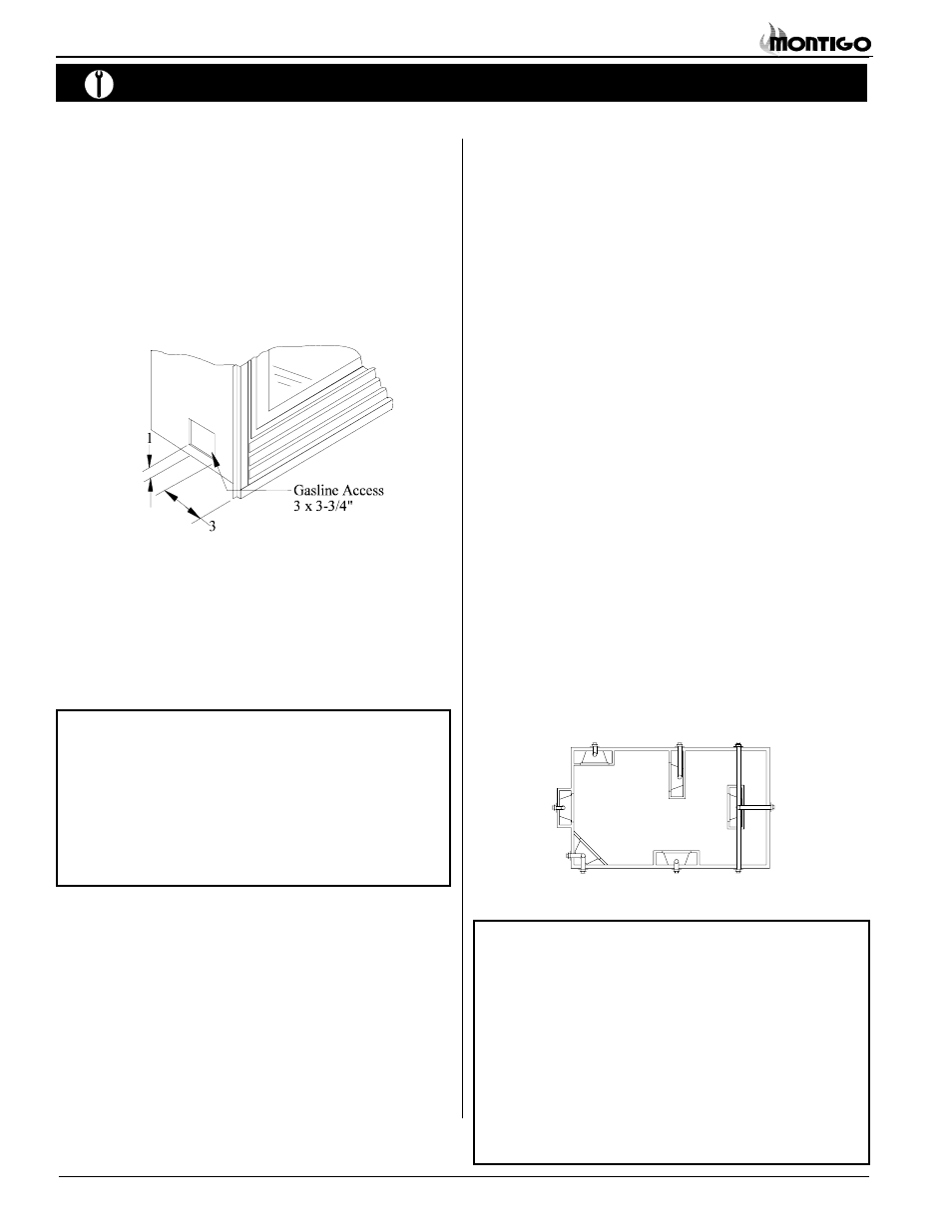
Installing The Gas Line
The gas line must be installed before finishing the W3400 Fireplace.
Natural Gas requires a minimum inlet gas supply pressure of 5.5"
W.C. & a manifold pressure of 3.5" W.C. Propane Gas requires a
minimum inlet gas supply pressure of 11" W.C. & a manifold pressure
of 10" W.C. Provision must also be made for a 1/8" N.P.T. plugged
tapping and be accessible for test gauge connection immediately
upstream of the gas supply controls to the appliance. The fireplace
gas connection and the main operating gas valve is located behind
the removable brass trim at the bottom of the unit and need only be
attached to the gas line with an approved fitting, as required by the
applicable installation codes.
Installation
Figure 6. Fireplace locations and vent terminations.
Note: After gas line is connected, each appliance connection,
valve and valve train must be checked while under
normal operating pressure with either a liquid solution, or
leak detection device, to locate any source of leak. Tighten
any areas where bubbling appears or leak is detected until
bubbling stops completely or leak is no longer detected.
DO NOT use a flame of any kind to test for leaks.
Installing The Remote Switch
The W3400's gas valve, located behind the lower brass trim, may be
connected to a wall switch or a thermostat. The valve is pre-wired and
completely self contained to generate its own power. DO NOT connect
any external power to it.
Refer to Figure 26 for wiring requirements.
Note: The switch location must not exceed 30' from the fireplace.
Figure 5. Gas line access.
During any pressure testing of the gas supply piping that excedes 1/2
psig (3.5 kPa), the appliance and its individual shutoff valve must be
disconnected from gas supply system.
When pressure testing the gas supply piping system at test pressures
of less than or equal to 1/2 psig (3.5 kPa), the appliance must be
isolated from the gas supply piping system by closing its individual
manual shutoff valve.
Vent terminations can be very hot. If the termination is less
than 7 feet above a public walkway, it should be fitted with a
certified Montigo Heat Guard. (Part no. PTKOG)
Do not obstruct, or attempt to conceal, the vent termination.
These actions will affect the operation of the fireplace, and
may be hazardous.
In heavy snow areas, take extra care to prevent snow buildup
from obstructing the vent termination.