Installation, Installing the fireplace shell, Framing – Montigo MW34 DV User Manual
Page 3: Clearances
Page 3 of 21
W3400 Gas Fireplace
Installing The Fireplace Shell
The fireplace may be installed in any location that is free of air
conditioning ducts, electrical wiring and plumbing. Safety, as well as
efficiency of operation, must be considered when selecting the
fireplace location. Try to select a location that does not interfere with
room traffic, has adequate ventilation, and offers an accessible
pathway for Direct Vent installation. Refer to page 4 - Vent Installation
for more information.
The fireplace dimensions are shown below:
Installation
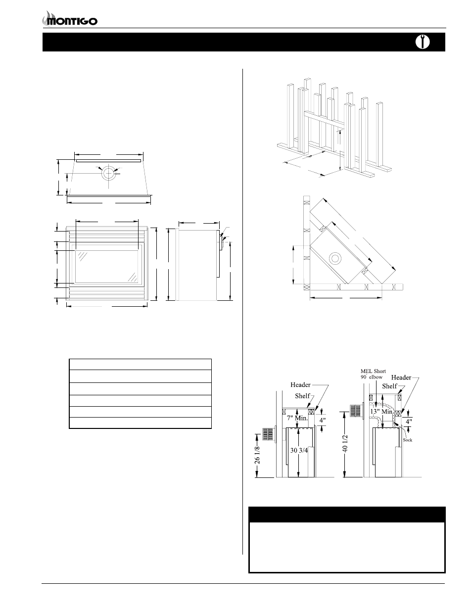
When installing a shelf over the top of the fireplace, the following
guidelines must be adhered to: For Rear Vent models (W3400R), the
minimum clearance from the top of the fireplace to a shelf is 7". For
Top Vent models (W3400DT), the minimum clearance is 13".
(Minimum 1" clearance must still be maintained around the vent
pipes.)
Figure 3. Corner framing dimensions.
Figure 2. Framing dimensions.
* When sheetrock is
not used behind the
fireplace, framing
depth may be
reduced to 15"
Framing
WARNING:
When this appliance is installed directly on carpeting, tile or any
combustible material other than wood flooring, it must be installed
on a metal or wood panel extending the full width and depth of
the appliance.
Rear Vent
Clearances
The W3400 clearances to combustible materials are:
Top - Rear Vent*
7"
Top - Top Vent*
†
13"
Back
0"
Side
1"
Floor
0"
Mantle**
10"
*
Clearance from the top of the fireplace to a combustible
ceiling within the fireplace enclosure.
** Refer to page 11.
†
If special short elbow (SEL90) is used with the Low Clearance
Sleeve (CRS30) the Top Clearance is 13".
If the standard elbow (MEL90) is used with the Low
Clearance Sleeve (CRS30) the Top Clearance is 15".
If the Low Clearance Sleeve (CRS30) is NOT used
over the elbow, the Top Clearance is 35".
Top Vent
34
24 1/2
32
12 1/8
4 3/4
4 3/4
Front View
Figure 1.
Fireplace dimensions.
15
26 1/8
32
Ø7
Ø4
34
C
15
31 1/2
Ø7
Ø4
8 3/4
33
15 3/4
36
22 1/4
42
33
59 3/8
Unprotected combustible walls which are perpendicular to the
fireplace opening, must not project beyond the shaded area shown in
Figure 19b.
For protection against freezing temperatures, it is recommended that
outer walls of the chase be insulated with a vapour barrier. This will
reduce the possibility of a cold-air convection current on the fireplace.
Figure 4. Framing for shelves over the fireplace.
W3400DT
W3400R