Installation, Model w3400r venting runs, Heat shields – Montigo MW34 DV User Manual
Page 9
Page 9 of 21
W3400 Gas Fireplace
Installation
Rear Vent
A. Through-The-Wall Rear Vent Installations
The W3400R has three possible installations which do not require
vertical lift:
1. Standard Installation.
Model W3400R Venting Runs
For the W3400R, there are two types of installations: A) Basic
Through-The-Wall Installations and B) Multi-Elbow Installations.
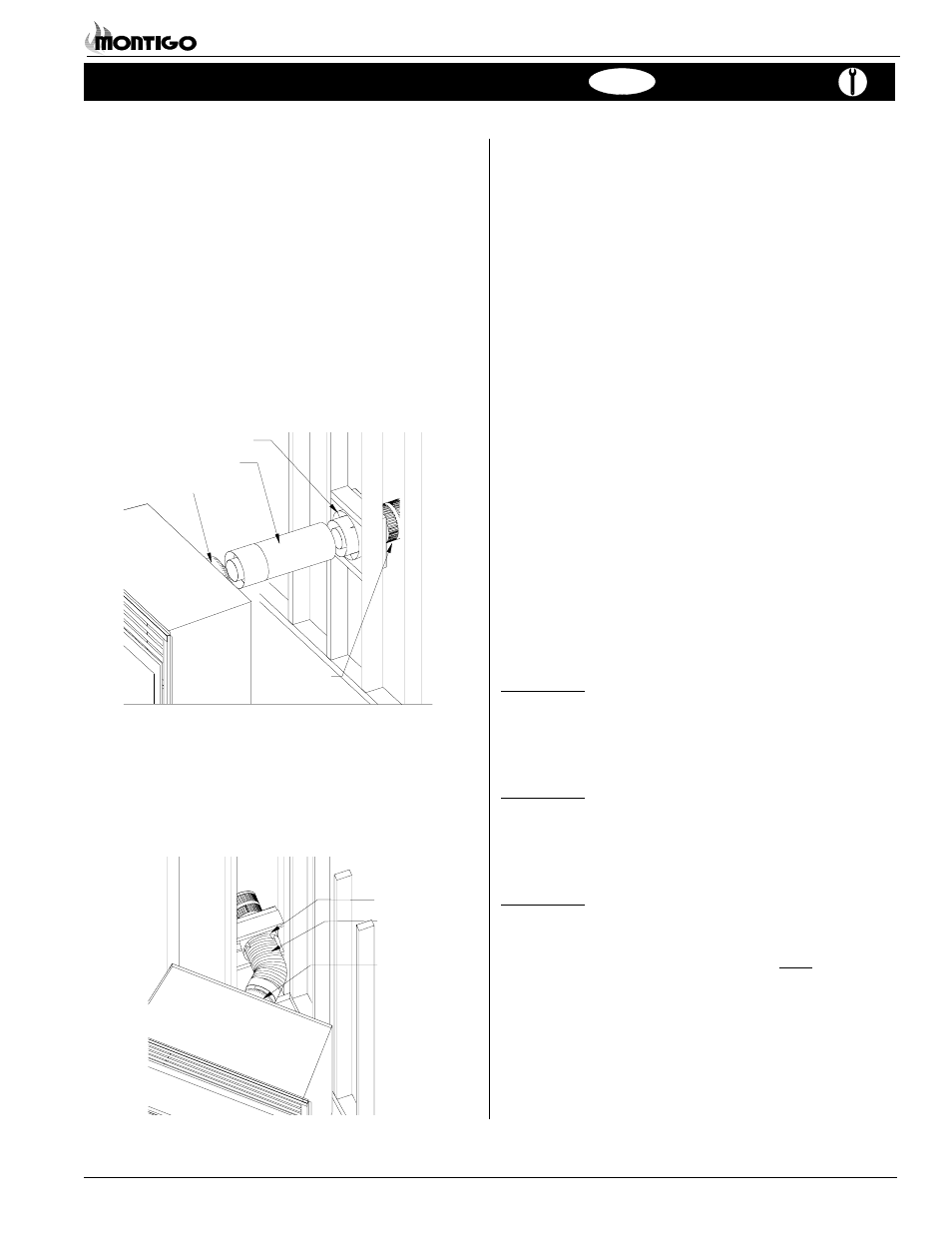
For standard installations, you may use the PXT-20 section, and a
termination. The height from the hearth to the center of the
termination is 26 1/8".
Note:
PXT extensions may be cut to desired length but must
never exceed 18".
Flue Collar
Heat Shield
EXT extension
ETKO
Termination
Figure 15. Extended installation.
Figure 16. Flex installation.
2. Corner Installation - 45° or less.
Use a PFL (12" or 20" compressed length) and a frame, if
appropriate. Flex may be turned to obtain desired degree of angle
required but must not exceed 45°.
Heat Shield
Flex
Termination
Flue Collar
Heat Shields
Due to high flue temperatures, heat shields are required on all W3400
installations (except those with vertical terminations) at the point where
the venting connects to the termination. With the heat shield, vent
clearances can be maintained at 1".
See Figure 8.
B. Multi-Elbow Installations
For more diffiicult installation situations, the W3400R may be installed
with 2 - 90° elbows and up to 15' of horizontal run. If using this
installation option, you must adhere to the following guidelines:
the first 90° elbow must be placed directly on the flue collar
you must have a minimum vertical lift of 50" (measured from the
hearth)
your vent run must fall within the limits set by Figure 19
Before you install any venting, you must determine whether the
venting run will be acceptable. Unacceptable venting can affect the
fireplace's combustion.
The Venting Graph
Measure the vertical height from the fireplace hearth to the centre of
the termination and the horizontal run from the from the fireplace flue
collar to the wall flange of the termination. Plot on the Venting Graph
(Fig. 19) with an 'X'.
If the 'X' falls on or above the top boundary of the shaded area, the
installation is acceptable.
Example A: (Acceptable Installation)
If the vertical dimension from the hearth is 84" and
the horizontal run to the wall flange of the vent
termination is 36", this would be an acceptable
installation.
Example B: (Acceptable Installation)
If the vertical dimension from the hearth is 90" and
the horizontal run to the wall flange of the vent
termination is 126", this would be an acceptable
installation.
Example C: (Unacceptable Installation)
If the vertical dimension from the floor of the fireplace
is 78" and the horizontal run to the wall flange of the
vent termination is 108", this would NOT be an
acceptable installation.