Installation, Model w3400t venting runs, Installation of top vent dv – Montigo MW34 DV User Manual
Page 6
Page 6 of 21
W3400 Gas Fireplace
Installation
Model W3400T Venting Runs
For the W3400T Top Vent there are two types of installations: A)
Through-The-Wall Installations and B) Vertical (Through-The-Roof)
Installations.
A) Through-The-Wall Installations
Before you install any venting, you must determine whether the
venting run will be acceptable. Unacceptable venting can affect the
fireplace's combustion.
The Venting Graph
Measure the vertical height from the fireplace hearth to the centre of
the termination and the horizontal run from the from the fireplace flue
collar to the wall flange of the termination. Plot on the Venting Graph
(Fig. 7) with an 'X'.
If the 'X' falls on or above the top boundary of the shaded area, the
installation is acceptable.
Example A: (Acceptable Installation)
If the vertical dimension from the hearth is 84" and
the horizontal run to the wall flange of the vent
termination is 36", this would be an acceptable
installation.
Example B: (Acceptable Installation)
If the vertical dimension from the hearth is 90" and
the horizontal run to the wall flange of the vent
termination is 126", this would be an acceptable
installation.
Example C: (Unacceptable Installation)
If the vertical dimension from the floor of the fireplace
is 78" and the horizontal run to the wall flange of the
vent termination is 108", this would NOT be an
acceptable installation.
Top Vent
0
12 24 36 48 60 72 84 96 108
132
120
144 156 168 180
Horizontal Run (in.)
Hearth
0
12
24
36
48
60
72
84
96
108
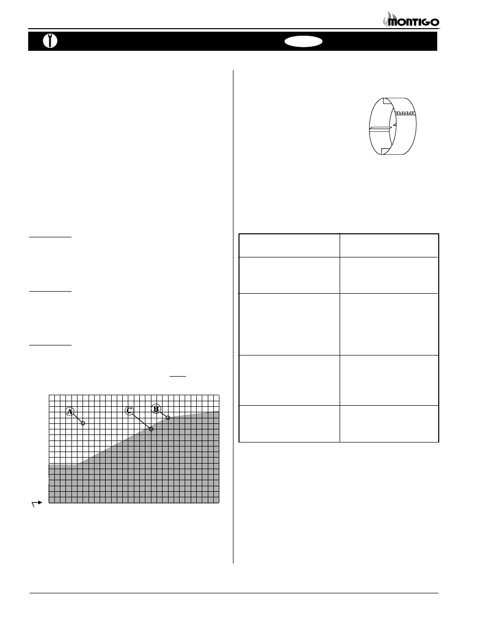
Heat Shields
Due to high flue temperatures, heat shields are required on all 34
Series Modular Direct Vent installations
(except those with vertical terminations) at
the point where the venting connects to the
termination. With the heat shield, vent
clearances can be maintained at 1".
Figure 7. W3400T Venting Graph
NOTES:
All dimension lengths for vertical or horizontal runs are
measured from center of the vent pipe.
Venting runs must fall within the limits set by the
venting graph (see Figure 7).
Figure 8.
Heat Shield. Install by sliding over the vent pipe where it
passes through combustible construction.
Installation Of Top Vent DV
The following venting components are available for the W3400T:
A - Termination
PTO-3 (3" length)
PTO-3F (3" length)
B - Stucco Kits
MSR (stucco frame)
MOSR (stucco can)
BSR (brick can)
D - Flex sections
PFL-1 (12" section)
PFL-18 (18" section)
PFL-2 (24" section)
PFL-3 (36" section)
PFL-4 (48" section)
E - Rigid sections
PEXT-1 (12" m/f section)
PEXT-2 (24" m/f section)
PEXT-3 (36" m/f section)
PEXT-4 (48" m/f section)
F - Elbows
PEL-90M (m/m 90° elbow)
PEL-90F (f/f 90° elbow)
PEL-90FM (f/m 90° elbow)