NavCom SF-2110 Quick Start Rev.A User Manual
Connect equipment, Run starutil-2110, Sf-2110 quick start guide
SF-2110 Quick Start Guide
Follow this Quick Start Guide to set up the standard
configuration of the SF-2110, designed for productivity
with minimal setup time.
The supplied CD-ROM (P/N 96-314001-3001) includes
guides with complete instructions for optimum
performance:
9
SF-2110 User Guide
9
StarUtil-2110 User Guide
9
SF-2110 Technical Reference Manual
Connect Equipment
1. Connect the supplied Positronic 9-Pin connector of the
serial cable (P/N 94-310260-3006LF) to Port A or Port B
of the SF-2110. Connect the DB9 end to the PC.
2. Mount the supplied L1/L-Band GPS Antenna
(P/N 82-001017-0001LF) to a mast. Locate the antenna
in an area with a 360º clear view of the sky.
3. Connect the supplied GPS antenna cable
(P/N 94-310261-3012LF) to the GPS Antenna. Connect
the other end to the TNC connector, labeled ANT 1, on
the receiver.
9
MODEL SF-2110R only: To track
StarFire™ signals, mount the L-Band
antenna (PN: 82-001018-0001LF) to a
mast. Connect the supplied GPS antenna
cable to the L-Band Antenna. Connect the
other end to the TNC connector, labeled
ANT 2, on the SF-2110R receiver.
4. Connect the supplied 110/220V AC power
cord into the supplied AC/DC power adapter
(P/N 82-020005-3001LF).
5. Connect the Positronic 9-pin end of the power adapter to
the receiver power port.
6. Plug the power cord into an AC receptacle.
7. Depress
the
On/Off switch on the front panel for more
than 3 seconds to power on the receiver. All LEDs
illuminate for 3-5 seconds during power-up.
Run StarUtil-2110
8. Insert the supplied CD-ROM (P/N 96-314001-3001)
into the PC CD-ROM drive.
9. Locate and double-click the file, StarUtil-2110.exe.
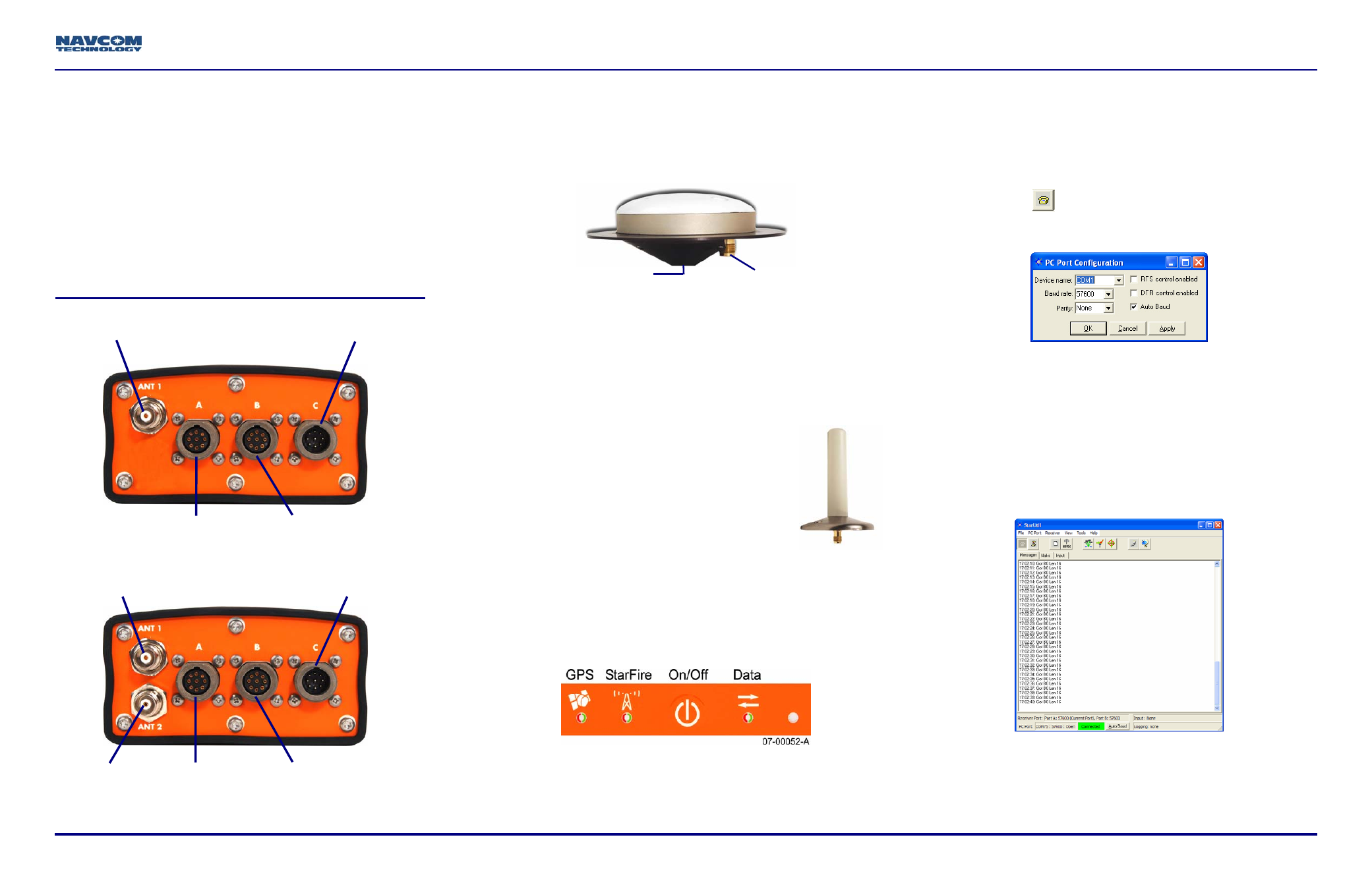
10. Click the
icon on the StarUtil toolbar to establish
communications between the PC and the SF-2110
receiver. The PC Port Configuration window opens.
11. In the Device name drop-down list, select the
PC COM port connected to the receiver.
12. Accept the default option, Auto Baud, or uncheck the
Auto Baud box and select a baud rate from the drop-
down list if the current receiver settings are known.
13. Click the OK button. The status bar at the bottom of
the StarUtil window indicates a successful
connection in green. NCT Messages scroll down the
Messages tab.
9
MODEL SF-2110R only: Select Tools > SF-2110
Configuration from the menu bar. The SF-2110
Configuration window opens. Select Dual as the
Number of Antenna.
TNC Connector
BSW Antenna Mount
TNC Connector 1
L1/StarFire Antenna
Power Port
SF-2110M
Port A
RS232
Port B
RS232/422
(switchable)
TNC Connector 1
L1 Antenna
Power Port
SF-2110R
Port B
RS232/422
(switchable)
Port A
RS232
TNC Connector 2
StarFire L-Band
96-310031-3001, Rev. A