Event latch interface, Event latch interface specifications, Event latch interface installation – NavCom VueStar Rev.B User Manual
Page 12
12
VueStar
™ Manual- Rev B
This section is dedicated to installation and information about the optional Event Latch Interface. The
Event Latch Interface is designed to allow VueStar™ to have greater compatibility with more aerial
cameras and survey sensors. The Event Latch interface eliminates the requirement of 3-6V DC with
50 Ohm load input impedance, and since it is powered by the receiver, it only requires a simple
setup.
This section covers the specifications and installation of the Event Latch Interface, and includes
limited information about setting up a receiver to capture events. For further information on
receiver setup please consult the SF2050 Manual.
The Event Latch Interface was designed to allow greater connectivity between the VueStar™ receiver
and Photogrammetry cameras. The Event Latch Interface (ELI) conditions and amplifies event pulse
output from cameras and other survey sensors so that the pulse can be successfully integrated with
the GPS receiver.
The ELI will support triggered rates of up to one pulse per second, provided that the pulse width is 10
microseconds or longer. The trigger source can be a simple off push button switch, or an electronic
switch such as an open/collect/ open drain device. Since the ELI is powered by the idle CAN bus on
the receiver the leakage current of the switch should be less then 1uA. If the trigger source is a real
electronic signal, then the pulse should have input voltage logic high 4—5.5V and logic low 0—0.4V
with a minimum 4mA sink current. The ELI will add a 12 microsecond delay to the time of an event.
The event latch is configured to trigger on the falling edge of the pulse. However, use of the
Event Latch Interface will condition the pulse appropriately, so the SF-2050M is able to accept
either rising or falling edge configurations (active high or active low).
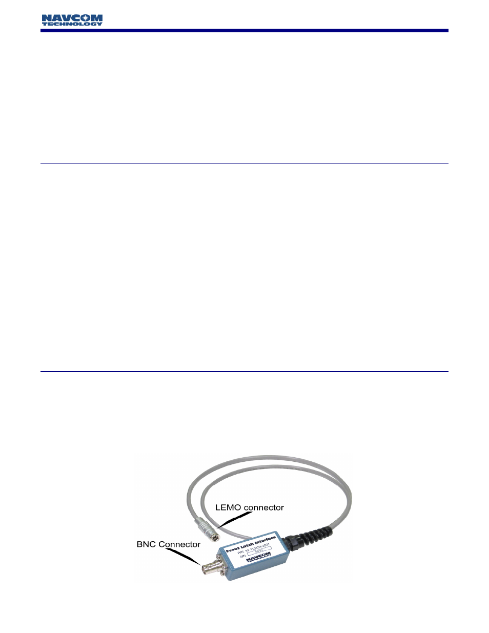
Installation of the Event Latch Interface is very simple. Connect the LEMO connector to the EVT MKR/
CAN connector located at the back panel of the SF-2050M GPS Receiver. Input into the ELI is
through a female BNC connector, where the center pin is the signal and the outer shell is the ground.
(Figure 4)
Event Latch Interface Specifications
Event Latch Interface Installation
Event Latch Interface
Figure 4: Event Latch Interface Connectors