3 the main board – Nevion SDI-TD-MUX-4 User Manual
Page 19
SDI-TD-MUX-4 / SDI-TD-DMUX-4
Rev. N
nevion.com | 19
HD
Output (Input) for 1.485 Gbps HD-SDI
(Multiplexed according to SMPTE 346M-2000).
BNC
OPT
Optical output (input) for 1.485 Gbps HD-SDI.
SC/UPC
GPI
General Purpose Interface (transistor drivers for
external alarm devices).
RJ-45
Unused inputs should be terminated to avoid alarms triggered by noise.
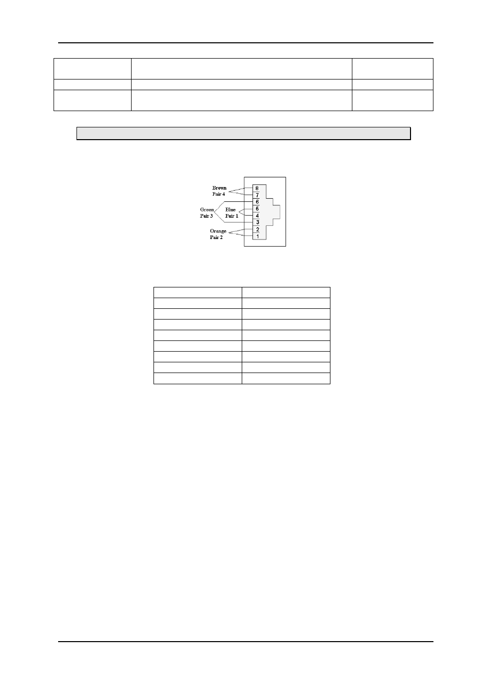
6.2.1 GPI/ Data connections RJ45
Figure 11: RJ45 Connector for GPI Signals
The below table show the signals available on the GPI connector on the backplane.
RJ45 Pin Number
Description
8
GND
7
Not Used
6
Not Used
5
Not Used
4
GPI2
3
GPI3
2
GPI0
1
GPI1
6.3 The main board
There are also a number of connectors on the board itself. None of these are intended for the
end-user. For proper operation, make sure there is a jumper in the lower position of the
connector located behind the DIP-switches (see Figure 12 and Figure 13 below).
The rear end of the boards (with the connector that mates to the backplane) is towards the
right side of the board. The boards must be mounted in a Flashlink FR-2RU-10-2 frame with
dedicated backplanes. Avoid inserting the SDI-TD-MUX-4 or SDI-TD-DMUX-4 board into a
wrong backplane, as this may cause electrical and/or mechanical damage to the main
boards and/or the backplanes.