5 configuration, 1 multicon gyda mode – Nevion SDI-TD-MUX-4 User Manual
Page 9
SDI-TD-MUX-4 / SDI-TD-DMUX-4
Rev. N
nevion.com | 9
5 Configuration
Both multiplexer and de-multiplexer cards are self-configuring in the sense that they will start
working according to default factory settings once power and input signals are applied.
Signals will be routed straight through without swapping/duplication and SD-SDI/DVB-ASI
will be detected and handled automatically.
Configuration parameters can be changed in two ways, via changes to the DIP switches or
via the system controller Multicon. The 8
th
DIP from the top of the module is labeled OVR. If
this DIP is set to the ON position, DIP switches 1-7 will control the module. Conversely, if it is
set to the OFF position, DIPs 1-7 are disregarded altogether and the module is controlled
from Multicon GYDA. Default settings as delivered from factory should be all DIPs in the Off
position. The module will then be under Multicon GYDA control.
5.1 Multicon GYDA mode
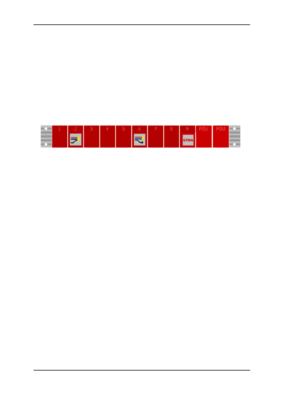
Figure 3: Multicon GYDA presentation of rack with an SDI-TD-MUX-4 module in position 2
Figure 3 shows how Multicon GYDA will present a rack equipped with an SDI-TD-MUX-4
module in rack position 2, an SDI-TD-DMUX-4 module in rack position 6, a Multicon GYDA
module in rack position 9 and a power supply unit in rack positions 10 and 11.
All functions of the card can be controlled through the Multicon GYDA control system. The
Multicon GYDA interface has an information page and a configuration page.
5.1.1 Information page
The information page shows a dynamic block diagram of the board and some additional
information text. The block diagram updates with the board status, showing missing signals
(by red crosses over the appropriate signal lines).
The text table on the information page gives additional information not easily conveyed in a
graphical manner.