Power supply modules, 1 how to access the modules, 2 how to configure the router and modules – Nevion 3GHD256256L User Manual
Page 10: 3 power supply module
3GHD256256L / SD256256L Rev. E
nevion.com | 10
3 Modules inside the Modular 256x256 router
In order to get an overview of the parts that form the Modular 256x256 Router this chapter
will highlight some of the main components.
3.1 How to access the modules
All active modules are accessible through the front of the router frame. If service or
inspection is required, open the unit from the front. The door may be removed for easy
access to the modules.
An important feature of all the modules in the Modular 256x256 Router frame is that they are
all hot-swappable. The user does not have to turn off the power in order to
remove/reinstall/replace a module with active components inside the Modular 256x256
Router.
When a board is hot-swapped and the reset button pushed, the router will restore the current
setting within seconds.
3.2 How to configure the router and modules
Setting up and configuring the router and its modules are done with the Nevion Configurator
software. The Nevion Configurator is shipped with the router, or could be downloaded from
For further instructions on router configuration, please see the online documentation in the
Nevion Configurator.
When the size of the router is changed by adding or removing of Main X-point
modules and/or I/O X-point modules, the Nevion Configurator must be
reconfigured to fit to the new router size.
3.3 Power supply module
Each Modular 256x256 router frame comes with four power supply modules. The first two
power supply modules are inserted in the slots marked with (A and C), and the second power
supply pair is inserted in the slots marked (B and D).
3.3.1 Module insertion
In order to insert a power supply module one must insert the module via the special plastic
guide rails into its position. Once the module is inserted, fix the module by lifting up the
handle on the front and pushing it to the upright position.
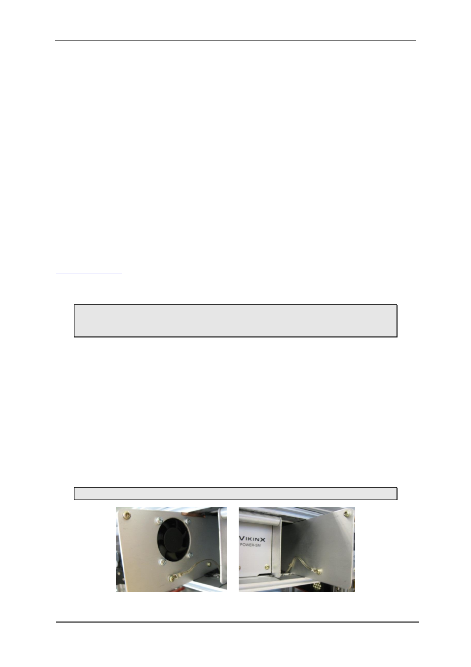
In frames where two ground straps are mounted in the upper power section, these must be
connected to the power supply modules as described in the pictures below.
Just unscrew the screws. Then remount through the eye of the ground straps.
Be aware the horizontal direction.