Nevion 3GHD256256L User Manual
Page 24
3GHD256256L / SD256256L Rev. E
nevion.com | 24
main plus 1 monitor line from its related X-point card and sending 32 signals to both X-point
cards.
The 32 SMA connectors are located at the upper, left end of the main backplane. Please
observe that the Flashlink modules must have dual outputs in order to provide two identical
signals to the main X-point cards. The lower X-point card is sending signals to Flashlink
output 1-8 (main matrix output 257-264) and the upper one is sending signals to Flashlink
output 9-16 (265-272).
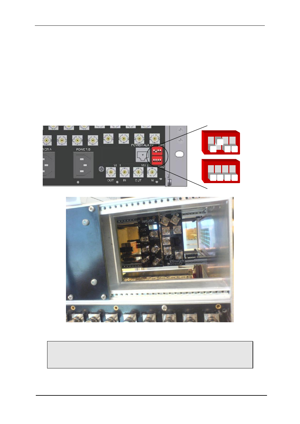
The Multicon GYDA has to be configured to an address that is not in conflict with the
Flashlink cards in the upper section of the router. This is done with the dip switches at the
lower backplane, located at the right side on the rear of the router. Configure it to card
number 5 by setting SW13 up and the rest down (ref. drawing).
Please observe the following notes when applying Flashlink modules in the VikinX
Modular 256x256 frame:
The function of the Flashlink section must be decided prior to ordering. This is
because the solution will be mounted and fully tested at Nevion before shipping.
The solution is not at all suitable for retrofitting and will therefore not be offered as
a solution for already delivered routers.
SW 14 13 12 11
SW 24 23 22 21