Nevion 3GHD256256L User Manual
Page 21
3GHD256256L / SD256256L Rev. E
nevion.com | 21
The 10 LEDs on the front of each X-point card indicate the following:
Diode
Red LED
Green LED
BEAT
Blinks when the μController is running
(heartbeat).
SYST.ERR A fault is detected on the card. The
system controller lights, or turns off
this LED. This is used for simplifying
the identification of a module.
SER.CH2
Blinks each time the μController of the
X-point card answers a message from
the system controller on
communication channel 2.
SER.CH1
Blinks each time the μController of the
X-point card answers a message from
the system controller on
communication channel 1.
TEST 1
No special function; for internal testing purpose only.
FAN 2
Fan error, when the fan speed is
outside its normal range. FAN2 is the
innermost fan on the X-point card.
The fan speed of FAN2 is in its normal
range. FAN2 is the innermost fan on
the X-point card.
PWR
Any of the voltages on the card is
outside their legal range.
All internal voltages are OK.
TEMP
The temperature of the card is outside
its legal range.
The temperature of the card is OK.
FAN1
Fan error, when the fan speed is
outside its normal range. FAN1 is the
outermost fan on the X-point card.
The fan speed of the first fan is in its
normal range. FAN1 is the outermost
fan on the X-point card.
EDH.ERR
Indicates EDH status for the selected
monitor output.
The monitoring output monitors the
selected input, but the EDH counter is
on the output.
Note that all alarm ranges are configurable from the system controller.
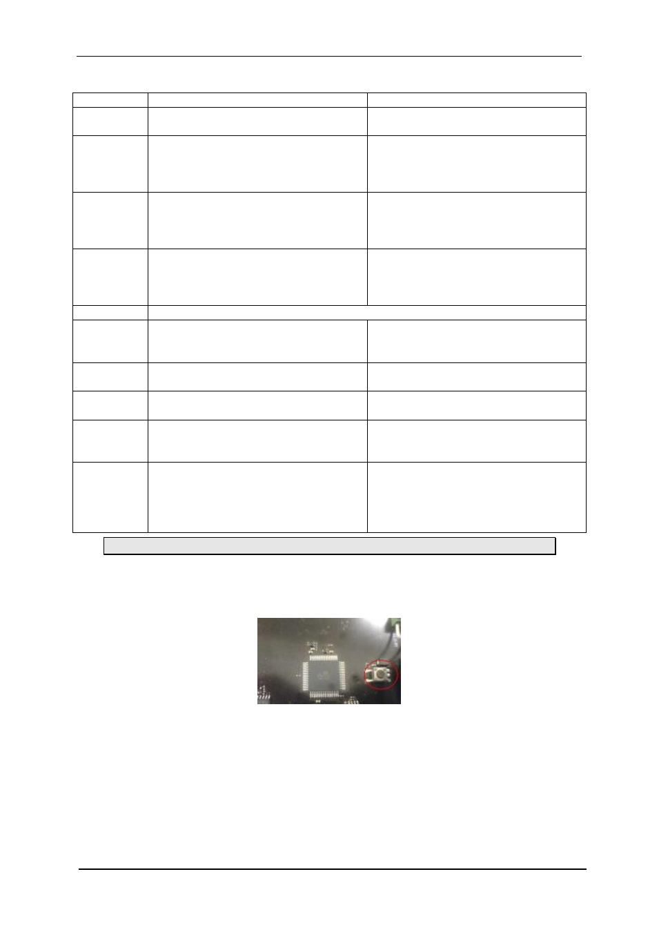
3.6.4 Service switch and reset button
There are one slide-switch and one push-button switch on the board, as shown in the figures
below.
The push-button switch (SW2001) is the RESET switch. When this button is pushed and
released, the μController of the X-point card resets and restarts its operation with its default
settings, or the settings stored in EEPROM.