Cpu header connector installation (x1) – NIStune TYPE 1 V.3.5 User Manual
Page 16
Nistune Type 1 Hardware Installation
Page 16 of 33
4. CPU Header Connector Installation (X1)
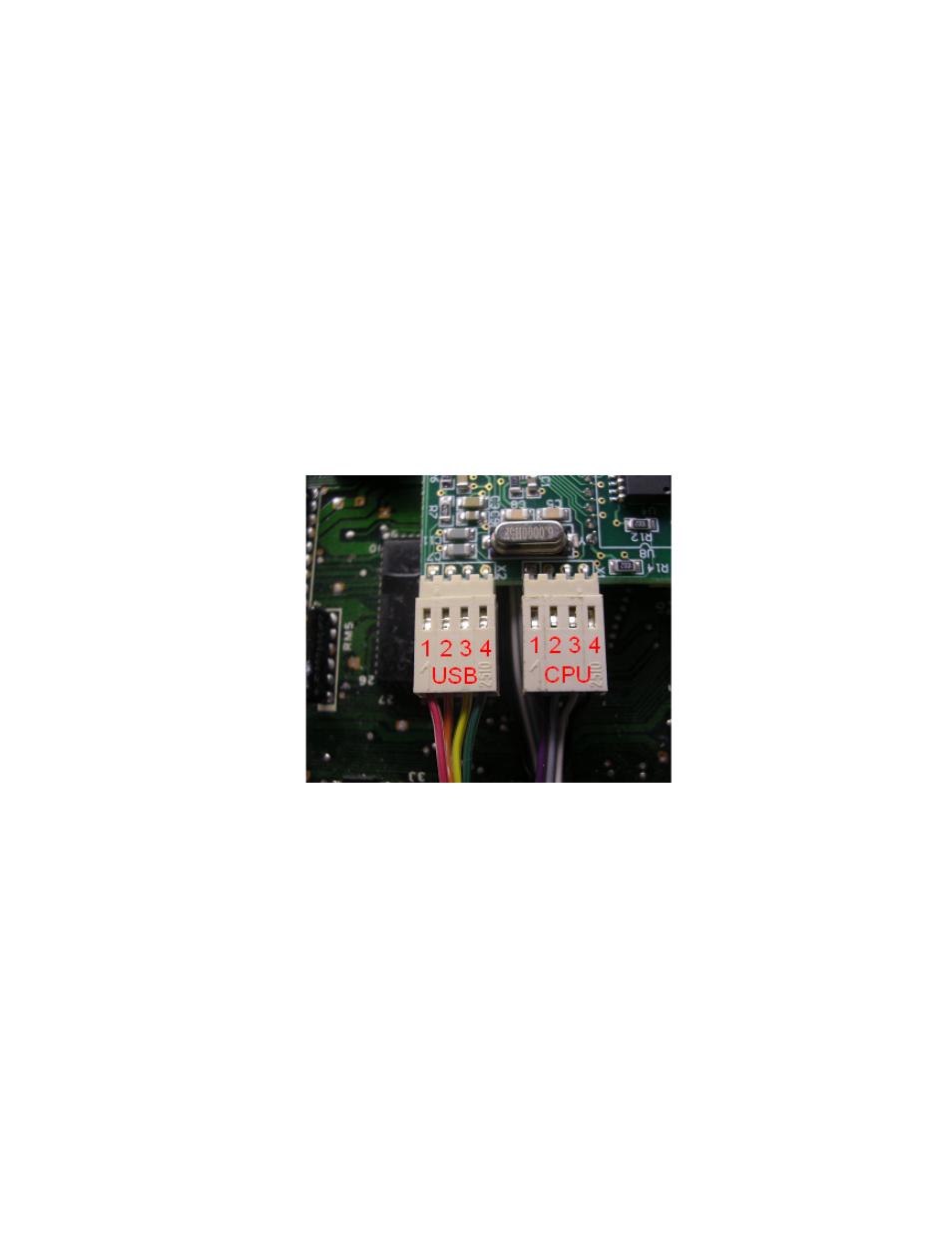
The Nistune board will come supplied with two header connectors. One is for the USB socket and
the other connects to the ECU processor (marked HD6802 or HD6303)
Early model ECUs will require direct connection to the processor, whilst later model ECUs provide
a silkscreen connector socket which needs to be soldered to.
The CPU header connector plugs into connector X1 on your Type 1 Nistune board and has a
marking on the connector to signify which pin is pin 1.
Important note: Due to recent changes in manufacture, colour coded wires will no longer be used
on Type 1 boards. The pin 1 will be identified by a marking on the connector itself as well as the
end of the wire.
1 - (R/W)
2 - (A14)
3 - (A15)
4 - (E)