NIStune TYPE 1 V.3.5 User Manual
Page 9
Advertising
Nistune Type 1 Hardware Installation
Page 9 of 33
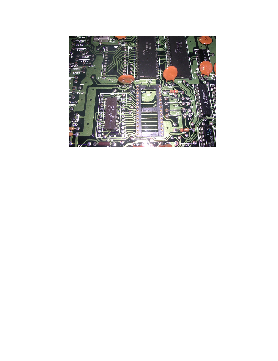
The below picture shows the removed ICs, installed 28 pin machine drilled socket and four wire
link jumpers installed in their new locations. Existing brown links can be reused into the new
jumper positions in the ECU.
Next remove R15 which is below J9/J10. This is no longer used with the Nistune board installed.
Note that You will no longer be able to use the factory ROM chip in this ECU once these jumpers
are changed.
Installation of the Nistune board now follows the same procedure as for other 6802 based ECUs
in the following sectionf of this document
Advertising