NIStune TYPE 1 V.3.5 User Manual
Page 23
Nistune Type 1 Hardware Installation
Page 23 of 33
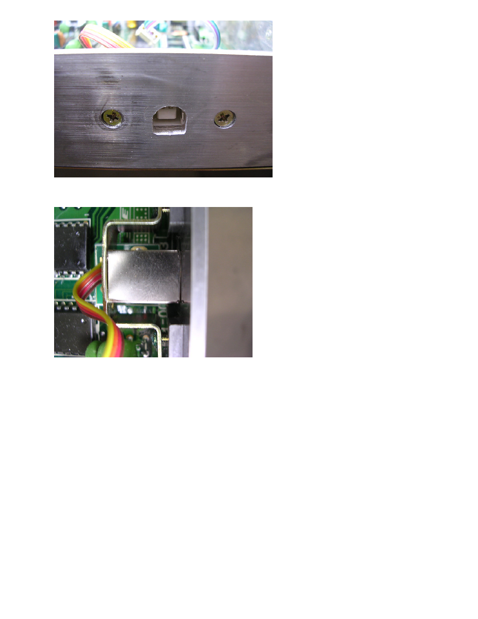
Then put the USB-B socket inside the bracket and refasten the bracket as seen below.
If your ECU has no daughter board then the USB connector board may face upwards. If you are
using a daughter board then ensure that the USB adaptor board faces downwards and does not
touch any other components.
Notes:
A31 RB20/ S13 CA18: It may be necessary to use longer screws to hold the original
potentiometer bracket.
U13 KA24E/EK10 MA09: The bracket has a single screw. You will need to fabricate a custom
bracket using two screw holes to hold the USB adaptor
HR31 RB20: We have found that there is no room for the USB connector. You may have to
relocate this bracket by drilling and tapping new holes in a different location if you wish to have
this fitted permanently
Ensure your USB socket is installed correctly and pressed against the ECU casing. This provides
a ground contact point for the USB shield to the board, to absorb electrical noise and prevent
unwanted USB disconnects during operation.